PPAP-3711
User s Manual
Revision: 010
Portwell Inc.
3F, No. 92, Nei-Hu Rd., Sec. 1, Taipei 114, Taiwan, R.O.C.
Headquarter: +886-2-2799-2020 Fax: +886-2-2799-1010
http://www.portwell.com.tw
Email: info@mail.portwell.com.tw
ITEM NO: B8980650
Table of Contents
Chapter 1 Introduction 2
1.1 Brief Guide for PPAP-3711VL ......................................................................2
1.2 Configuring the System Board......................................................................4
1.3 Memory ..............................................................................................5
Chapter 2 Getting Started 6
2.1 Installing a CF (Compact Flash) Card ..........................................................6
2.2 Upgrading the RAM Module .........................................................................6
2.3 Replace the Battery ......................................................................................7
2.4 Installing a Different Processor .....................................................................8
2.5 Hardware Configuration Setting....................................................................8
Chapter 3 Appendix 14
3.1 GPIO Sample code.....................................................................................14
3.2 Watch-Dog Timer Sample code..................................................................18
3.3 Reset To Default Sample code...................................................................20
1
NAR-5060 User’s Manual
Chapter 1 Introduction
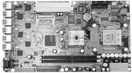
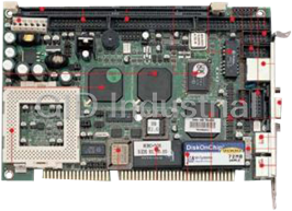
1.1 Brief Guide for PPAP-3711VL
The PPAP-3711VL all-in-one half-sized network appliance system board is designed to fit a high
®
performance Celeron™ and Pentium 4 based processor and compatible for high-end computer
system application. It is made to meet today's demanding pace, and keep complete compatibility
with hardware and software designed for the IBM PC/AT. It's beneficial to build up a high
performance and high data availability system for VARs, or system integrators.
® ® ®
This single board computer can run with Intel FC-PGA Celeron™ or Intel FC-PGA Pentium 4
processors (Speed up to 2.8GHz), and 184-pin DDR up to 2GB. The enhanced on-board PCI
IDE interface support 2 drives up to PIO mode 4 timing and Ultra DMA/100 synchronous mode
feature. The on-board Super I/O Chipset integrates only two serial ports, which are driven by
two high performance 16C550-compatible UARTs to provide 16-byte send/receive FIFOs.
Besides, the two Universal Serial Bus ports provide high-speed data communication between
peripherals and PC.
The A built-in Watch-dog Timer function helps to monitor your system status. The on-board
Flash ROM is used to make the BIOS update easier. An AC/DC adaptor power input jack is
provided for AT mode operation. The high precision Real Time Clock/calendar is built to support
Y2K for accurate scheduling and storing configuration information. All of these features make
PPAP-3711VL excellent in stand-alone applications.
Fig. 3-1
2
NAR-5060 User’s Manual
System Architecture
The following illustration of block diagram will show how PPAP-3711VL be a highly integrated
system solution. The most up-to-date system architecture of PPAP-3711VL, includes two main
VLSI chips, 845GL/GV Host Bridge and 82810DB, to support FC-PGA Celeron/P4 processor,
DDR, PCI bus interface, USB 2.0 port, SMBus communication, and Ultra DMA/100 IDE Master.
The on-board super I/O chip, W83627HF, supports two UARTs.
® ®
PPAP-3711VL built-in Socket 478 to support Intel FC-PGA Celeron™/Pentium 4 processor
®
(both for 400/533 FSB bus only) for high performance and cost-effective application. The Intel
Celeron™ processor is the next addition to the P6 micro architecture processor product lines.
®
The Intel Celeron™ processor, like the Intel Pentium Pro and Intel Pentium II processor,
features a Dynamic Execution micro-architecture and also executes MMX technology
instructions for enhanced media and communication performance. However, the FC-PGA
®
Pentium 4 processor provides 512K L2 Cache.
The North Bridge 845GL/GV provides a completely integrated solution for the system controller
and data path components in a Celeron™ processor system. It provides a 64-bit GTL+ based
host bus interface, optimized 64-bit DRAM interface without ECC to support two 2.5V DDR
memory module at the maximum bus frequency of 533 MHz, and 32-bit PCI bus interface to
support on-board PCI device.
The South Bridge, 82810DB, provides one channel dedicated Ultra DMA-100 IDE master/slave
interface, full Plug-and-Play compatibility, and one channel CF slot, Advanced Programmable
Interrupt Controller (APIC) interface on PPAP-3711VL. It also supports 4-port Universal Serial
Bus (USB 2.0) and PCI 2.1 Compliance operation.
The Super I/O chip W83627HF integrates two high-speed serial ports.In PPAP-3711VL, it
contains Watch-dog Timer (WDT) enabled by Software(BIOS). and Eight bit GPIO, Besides, an
advanced feature is used on PPAP-3711VL to support detection of CPU temperature.
Provides 64Kbit nVRAM(non-volatile RAM), and One 2x5 pin connector for VGA supported.
All detailed operating relations are shown in Fig. 1-1 PPAP-3711VL System Block Diagram.
3
NAR-5060 User’s Manual
Fig.1-1 PPAP-3711VL System Block Diagram
1.2 Configuring the System Board
Product Specifications
® ®
Main processor Intel Celeron™/Pentium 4 Processors. (Speed
up to 2.8GHz)
BIOS Award system BIOS with 64Kb Flash ROM to support DMI, PnP,
Redirect to console.
Main Memory Two 184-pin DDR socket, supporting 2.5V DDR up to 2GB
®
L2 Cache Memory
128KB/512KB PBSRAM built in (Celeron™/Pentium 4) CPU
module
®
Intel 845GV
Chipset
IDE Interface
One on-board DMA33 IDE channel to support two IDE devices
Default support 2.5" IDE devices only (3.5" IDE requires a
converting cable)
Serial Ports One DB9 Connector for connecting to console
One internal Pin pair connector for optional LCD/Key pad module
4
NAR-5060 User’s Manual
(Portwell Proprietary)
USB Interface
Support two USB 2.0 ports for high speed I/O peripheral devices
Auxiliary I/O System reset switch, Power LED, LAN activity LED, HDD LED
Interfaces
interface
Watchdog Timer 255 intervals from 0.5 min. to 254.5 min. by software programming
Power Inlet One standard 20-pin ATX power connector
One on-board DC input jack
PCI Golden Finger One PCI golden finger edge connector for PCI connection
Hardware Monitor On-board hardware monitor for:
CPU fan x 1
System fan x 2
System voltages: +5V and +12V
Power Good On-board power good generator with reset time, 300ms~500ms
1.3 Memory
This PPAP-3711VL provides one 184-pin DDR socket. The maximum memory size is 2GB.
Normally, the DDR used could be 2.5V DDR with speed less than 70ns (-7), you need to use
DDR with speed less than 70ns (-7). It is better to use PC2700-compliant memory chip on your
system.
For system compatibility and stability, don't use memory module without brand. You can also
use the single or double-side DDR without parity check and ECC function.
Watch out the contact and lock integrity of memory module with socket, it will impact on the
system reliability. Follow normal procedure to install your DDR RAM module into memory socket.
Before locking, make sure that the module has been fully inserted into card slot.
NOTE: For maintaining system stability, don't change any of DDR parameters in BIOS setup to
upgrade your system performance except for getting technical information.
5
NAR-5060 User’s Manual
Chapter 2 Getting Started
This section describes how the hardware installation and system settings should be done.
2.1 Installing a CF (Compact Flash) Card
1. To install a compact flash card, it needs only to insert the CF card into the white socket on
the adaptor board (Fig. 2-1)(Fig. 2-2)
Fig. 2-1 Fig. 2-2
2.2 Upgrading the RAM Module
In case of upgrading system RAM module, follow these steps:
1. Pull out the lock arms on both side and the RAM module springs up automatically. (Fig.2-3)
2. Press down gently on both left and right edges of the module (Fig.2-4) until it "clicks".
3. Then reappear step 1 to 2 to install more RAM module.(Fig. 2-5)
Fig. 2-3 Fig. 2-4
6
NAR-5060 User’s Manual
Fig. 2-5
2.3 Replace the Battery
In case of replacing the battery, follow these steps:
Fig. 2-6 Fig. 2-7
1. Press the metal hook backward. (Fig.2-6)
2. The battery springs automatically. (Fig.2-7)
3. Replace a new one and press it back with fingertip.
7
NAR-5060 User’s Manual
2.4 Installing a Different Processor
The system was designed to self-detect its CPU speed. So it does not require any system
adjustment.
Fig. 2-8 Lift the handling lever of CPU socket Fig. 2-9 insert CPU into theSocket
outwards and upwards to the other end.
2.5 Hardware Configuration Setting
This section gives the definitions and shows the positions of jumpers, headers and connectors.
All of the configuration jumpers on PPAP-3711VL are in the proper position. The default settings
set by factory are marked with a star (★ ).
2.5.1 Jumpers
In general, jumpers on the single board computer are used to select options for certain features.
Some of the jumpers are user-configurable, which allows system enhancement. The others are
for testing purpose only and should not be altered. To select any option, cover the jumper cap
over (Short) or remove (NC) it from the jumper pins according to the following instructions. Here
NC stands for "Not Connected". (Please refer to Fig. 2-10 for detail jumper positions)
8
NAR-5060 User’s Manual
mPGA478B
J4 J5
5
5
9
10 10
10
J6
13
J8
LAN6 26
20
19
J9 FWH
2 2 2 2
J2 J3
J7
J15
J19
J10
4 4 4
LAN5 JP1
BAT
J23
J16
SIO
J11 J12 J13 J14
J20 J21 J22 J17 J18
J24
J25
2 10
LAN4
7
J26
LAN3
845GV/GL
J27
ICH4
LAN2
J28
JP2
LAN1
J29
J30
JP3
DIMM1
10 5
J34 J33
9 2 DIMM2
J32
4
2 10
J31
J40
J39
J35
6 J36
PW1 40 J38
39
44
J37
43
Fig.2-10 PPAP-3711VL Jumper Locations
2.5.2 Connectors
I/O peripheral devices and Flash disk will be connected to these interface connectors or DOC
socket located on this single board computer.
Connector Function Remark
JP1 Secondary IDE Select Shot: Master / Open: Slave
JP2 Clean CMOS 1-2: Normal , 2-3: Clean
JP3 WDT Select Shot: WDT Reset / Open: SMI
J2 K/B, M/S
J3 CRT
J4 Small 4 pin header
J5 USB
J7 Parallel port
J8 GPIO
J11 LAN6_LED
J12 LAN5_LED
J13 LAN4_LED
J14 LAN3_LED
J17 Load_Default
J18 Reset
J20 LAN2_LED
J21 LAN1_LED
J22 HDD_PowerLED
J30 Load_Default
J31 COM2
J33 HDD_PowerLED
J34 USB
9
NAR-5060 User’s Manual
Pin Assignments of Connectors
●
JP1: Secondary IDE Select
Pin No. Signal Description
Shot Master
NC Slave
●
JP2: Clean CMOS
Pin No. Signal Description
1–2 Normal
2–3 Clean CMOS
●
JP3: WDT Select
Pin No. Signal Description
Shot WDT Reset
NC WDT SMI
●
J2: K/B , M/S
Pin No. Signal Description
1 MDAT
2
3 GND
4 VCC
5 MCLK
6 KDAT
7
8 GND
9 VCC
10 KCLK
●
J3: CRT
Pin No. Signal Description
1 RED
2 GREEN
3 BLUE
4 VSYNCR
5 HSYNCR
6 DDCCL
7 GND
8 DDCDA
9 GND
10
10
NAR-5060 User’s Manual
●
J4: Small 4 pin header
Pin No. Signal Description
1 +12V
2 GND
3 GND
4 VCC
●
J5/J34: USB Header
Pin No. Signal Description
1 VCC2/VCC4
2 GND3/GND5
3 DATA2/DATA4
4 GND3/GND5
5 DATA2+/DATA4+
6 DATA3+/DATA5+
7 GND2/GND4
8 DATA3-/DATA5-
9 GND2/GND4
10 VCC3/VCC5
●
J7: Parallel port
Pin No. Signal Description Pin No. Signal Description
1 P_STB# 2 P_PD0
3 P_PD1 4 P_PD2
5 P_PD3 6 P_PD4
7 P_PD5 8 P_PD6
9 P_PD7 10 ACK#
11 BUSY 12 PE
13 SLCT 14 P_AFD#
15 ERR# 16 P_INIT#
17 P_SLIN# 18 GND
19 GND 20 GND
21 GND 22 GND
23 GND 24 GND
25 GND 26 N/A
●
J8: GPIO
Pin No. Signal Description Pin No. Signal Description
1 VCC 2
3 Di8 4 Do8
5 Di7 6 Do7
7 Di6 8 Do6
9 Di5 10 Do5
11 Di4 12 Do4
13 Di3 14 Do3
15 Di2 16 Do2
17 Di1 18 Do1
19 GND 20 GND
11
NAR-5060 User’s Manual
●
J11: LAN6_LED
Pin No. Signal Description
1 L6_1000#
2 L6_LINK LED#
3 L6_100#
4 L6_ACT
●
J12 : LAN5_LED
Pin No. Signal Description
1 L5_1000#
2 L5_LINK LED#
3 L5_100#
4 L5_ACT#
●
J13 : LAN4_LED
Pin No. Signal Description
1 L4_1000#
2 L4_LINK LED#
3 L4_100#
4 L4_ACT#
●
J14 : LAN3_LED
Pin No. Signal Description
1 L3_1000#
2 L3_LINK LED#
3 L3_100#
4 L3_ACT#
●
J17/J30: Load_Default
Pin No. Signal Description
1 PRE#
2 GND
●
J18 : RESET
Pin No. Signal Description
1 GND
2 RESET
●
J20 : LAN2_LED
Pin No. Signal Description
1 L2_1000#
2 L2_LINK LED#
3 L2_100#
4 L2_ACT#
12
NAR-5060 User’s Manual
●
J21 : LAN5_LED
Pin No. Signal Description
1 L1_1000#
2 L1_LINK LED#
3 L1_100#
4 L1_ACT#
●
J22/J33: HDD_Power LED
Pin No. Signal Description
1 GND
2 VCC
3 HDD_ACT
4 VCC
●
J31: COM2
Pin No. Signal Description
1 DCD#2
2 RXD#2
3 TXD#2
4 DTR#2
5 GND
6 DSR#2
7 RTS#2
8 CTS#2
9 RI#2
10
13
NAR-5060 User’s Manual
Chapter 3 Appendix
3.1 GPIO Sample code
/*
* led.c:
*
* Copyright (C) 2001 DeanSoft Co.,Ltd
* Copyright (C) 1998,2000,2001 Alessandro Rubini
*
* This program is free software; you can redistribute it and/or modify
* it under the terms of the GNU General Public License as published by
* the Free Software Foundation; either version 2 of the License, or
* (at your option) any later version.
*
* This program is distributed in the hope that it will be useful,
* but WITHOUT ANY WARRANTY; without even the implied warranty of
* MERCHANTABILITY or FITNESS FOR A PARTICULAR PURPOSE. See the
* GNU General Public License for more details.
*
* You should have received a copy of the GNU General Public License
* along with this program; if not, write to the Free Software
* Foundation, Inc., 59 Temple Place, Suite 330, Boston, MA 02111-1307, USA.
*/
#include
#include
#include
#include
#include
#include
#include
#include
#include /* linux-specific */
#ifdef __GLIBC__
# include
#endif
// #define DEBUG
static unsigned int pmbase=0;
unsigned int read_port(unsigned int port,int size)
{
static int iopldone = 0;
unsigned int val=0;
14
NAR-5060 User’s Manual
if (port > 1024) {
if (!iopldone && iopl(3)) {
fprintf(stderr, " iopl(): %s\n", strerror(errno));
return 0;
}
iopldone++;
} else if (ioperm(port,size,1)) {
fprintf(stderr, " ioperm(%x): %s\n", port, strerror(errno));
return 0;
}
if (size == 4) {
val=inl(port);
#ifdef DEBUG
printf("Read_port:(0x%04x)=>0x%08x\n", port, val);
#endif
} else if (size == 2) {
val=inw(port);
#ifdef DEBUG
printf("Read_port:(0x%04x)=>0x%04x\n", port, val);
#endif
} else {
val=inb(port);
#ifdef DEBUG
printf("Read_port:(0x%04x)=>0x%02x\n", port, val);
#endif
}
return(val);
}
static int write_port(unsigned int port, unsigned int val,int size)
{
static int iopldone = 0;
#ifdef DEBUG
printf("Write_Port(0x%04x)<=0x%x\n", port, val);
#endif
if (port > 1024) {
if (!iopldone && iopl(3)) {
fprintf(stderr, "iopl(): %s\n", strerror(errno));
return 1;
}
iopldone++;
} else if (ioperm(port,size,1)) {
fprintf(stderr, "ioperm(%x): %s\n", port, strerror(errno));
return 1;
}
if (size == 4)
outl(val, port);
else if (size == 2)
15
NAR-5060 User’s Manual
outw(val&0xffff, port);
else
outb(val&0xff, port);
return 0;
}
void led_init()
{
unsigned int rval=0,mval=0;
// program bit 31,30,29 of PCR GENCFG to 1,1,1
write_port(0xCF8,0x800038B0,4);
rval=read_port(0xCFC,4);
mval=rval | 0xe0000000;
write_port(0xCF8,0x800038B0,4);
write_port(0xCFC,mval,4);
// program bit 8 of PCR XBCS to 0
write_port(0xCF8,0x8000384C,4);
rval=read_port(0xCFC,4);
mval=rval & 0xfffffeff;
write_port(0xCF8,0x8000384C,4);
write_port(0xCFC,mval,4);
// raed Power Management base address
write_port(0xCF8,0x80003B40,4);
rval=read_port(0xCFC,4);
pmbase=rval&0xFFC0;
}
//
// pos= 1~8 ,flag=1/0
//
void led_onoff(int pos, int flag)
{
unsigned int led=0;
switch (pos) {
case 1: // (D9) Bit5: 0-> led ON, 1-> led OFF
led = read_port(pmbase+0x37,1);
led=( flag==1 ?(led & 0xDF) : (led | 0x20));
write_port(pmbase+0x37,led,1);
break;
case 2: // (D10)Bit4: 0-> led ON, 1-> led OFF
led=read_port(pmbase+0x37,1);
led=( flag==1 ?(led & 0xEF) :(led | 0x10));
write_port(pmbase+0x37,led,1);
break;
case 3: // (D11)Bit3 0-> led ON, 1-> led OFF
led=read_port(pmbase+0x37,1);
led=( flag==1 ?(led & 0xF7) :(led | 0x08));
write_port(pmbase+0x37,led,1);
16
NAR-5060 User’s Manual
break;
case 4: // (D12)Bit2: 0-> led ON, 1-> led OFF
led=read_port(pmbase+0x37,1);
led=( flag==1 ?(led & 0xFB) :(led | 0x04));
write_port(pmbase+0x37,led,1);
break;
case 5: // (D13)Bit1: 0-> led ON, 1-> led OFF
led=read_port(pmbase+0x37,1);
led=( flag==1 ?(led & 0xFD) :(led | 0x02));
write_port(pmbase+0x37,led,1);
break;
case 6: // (D14)Bit0: 0-> led ON, 1-> led OFF
led=read_port(pmbase+0x37,1);
led=( flag==1 ?(led & 0xFE) :(led | 0x01));
write_port(pmbase+0x37,led,1);
break;
case 7: // (D15)Bit0: 0-> led ON, 1-> led OFF
led=read_port(pmbase+0x35,1);
led=( flag==1 ?(led & 0xFE) :(led | 0x01));
write_port(pmbase+0x35,led,1);
break;
case 8: // (D16)Bit0: 0-> led ON, 1-> led OFF
led=read_port(pmbase+0x34,1);
led=( flag==1 ?(led & 0xFE) :(led | 0x01));
write_port(pmbase+0x34,led,1);
break;
default:
}
}
#define ON 1
#define OFF 0
int main(int argc, char **argv)
{
// unsigned int i, n, port, size, error = 0;
// int i;
setuid(0); /* if we're setuid, force it on */
led_init();
#if 0
led_onoff(1,ON);
led_onoff(2,ON);
led_onoff(3,ON);
led_onoff(4,ON);
led_onoff(5,ON);
led_onoff(6,ON);
led_onoff(7,OFF);
led_onoff(8,OFF);
#endif
#if 0
for(i=0;i<50000;i++) {
17
NAR-5060 User’s Manual
led_onoff(1,ON);
sleep(10);
led_onoff(1,OFF);
}
#endif
#if 1
led_onoff(1,ON);
led_onoff(2,ON);
led_onoff(3,ON);
led_onoff(4,ON);
led_onoff(5,ON);
led_onoff(6,ON);
led_onoff(7,ON);
led_onoff(8,ON);
#endif
}
3.2 Watch-Dog Timer Sample code
Watch Dog Timer is a special function; the user can monitor and control the system via software
or hardware implementation. If the implementation does not respond in seconds, the system will
be rebooted automatically. With this mechanism, the lost or damage can be minimized, when
there is not monitoring personnel onsite.
Following list are PPAP-3711 Watch Dog Timer sample Code, this is for reference only:
/*
* PPAP-3711VL Watch Dog Sample:
*
* Copyright (C) 2001 Portwell Inc.
* Copyright (C) 1998,2000,2001,2002,2003. Chris Chiu
*
* This program is free software; you can redistribute it and/or modify
* it under the terms of the GNU General Public License as published by
* the Free Software Foundation; either version 2 of the License, or
* (at your option) any later version.
*
* This program is distributed in the hope that it will be useful,
* but WITHOUT ANY WARRANTY; without even the implied warranty of
* MERCHANTABILITY or FITNESS FOR A PARTICULAR PURPOSE. See the
* GNU General Public License for more details.
*
* You should have received a copy of the GNU General Public License
* along with this program; if not, write to the Free Software
* Foundation, Inc., 59 Temple Place, Suite 330, Boston, MA 02111-1307, USA.
*/
#include
#include
#include
18
NAR-5060 User’s Manual
#include
#include
#include
#include
#include
#include
#include /* linux-specific */
#ifdef __GLIBC__
# include
#endif
unsigned int read_port(unsigned int port,int size)
{
static int iopldone = 0;
unsigned int val=0;
if (port > 1024) {
if (!iopldone && iopl(3)) {
fprintf(stderr, " iopl(): %s\n", strerror(errno));
return 0;
}
iopldone++;
} else if (ioperm(port,size,1)) {
fprintf(stderr, " ioperm(%x): %s\n", port, strerror(errno));
return 0;
}
if (size == 4) {
val=inl(port);
#ifdef DEBUG
printf("Read_port:(0x%04x)=>0x%08x\n", port, val);
#endif
} else if (size == 2) {
val=inw(port);
#ifdef DEBUG
printf("Read_port:(0x%04x)=>0x%04x\n", port, val);
#endif
} else {
val=inb(port);
#ifdef DEBUG
printf("Read_port:(0x%04x)=>0x%02x\n", port, val);
#endif
}
return(val);
}
static int write_port(unsigned int port, unsigned int val, int size)
{
static int iopldone = 0;
19
NAR-5060 User’s Manual
#ifdef DEBUG
printf("Write_Port(0x%04x)<=0x%x\n", port, val);
#endif
if (port > 1024) {
if (!iopldone && iopl(3)) {
fprintf(stderr, "iopl(): %s\n", strerror(errno));
return 1;
}
iopldone++;
} else if (ioperm(port,size,1)) {
fprintf(stderr, "ioperm(%x): %s\n", port, strerror(errno));
return 1;
}
if (size == 4)
outl(val, port);
else if (size == 2)
outw(val&0xffff, port);
else
outb(val&0xff, port);
return 0;
}
void ppap100_wdt_enable ( ) {
read_port(0x433,1);
}
int main(int argc, char **argv)
{
ppap100_wdt_enable();
}
3.3 Reset To Default Sample code
“ Reset To Default” can provide a programming button.
Below is sample code for PPAP-3711 Reset To Default function
; For PPAP-3711, RESET to Default testing
; By Frank Hsu , 10/01/2003
;
; Reset to default status can be read from ICH4_GPI6.
; After Power On reset, GPI6 = low ( 0 )
20
NAR-5060 User’s Manual
; If Reset to Default (RST2DF) Button pressed ( Triggered )
; ,then GPI6 will be latch to high ( 1 ).
;
; RST2DF register can be cleared by ICH4_GPO19.
; Write a pulse timing ( High1_low_high2 ) to clear RST2DF to 0.
; High1 : output GPO19 high , and keep 10 us.
; Low : output GPO19 low , and keep 10 us.
; High2 : output GPo19 high again , and keep high always.
;
;
; Programming Guide :
; PG_Step1 : Enable ACPI IO port assignment and get PMBASE, then save to
; EBX_Bit[31..16]
;
; First : GPI_ROUT bit[13,12] P [0,0] : Let GPI6 not evoke SCI.
; Write GPI_Rout bit[13,12] to [0,0] for no effect on GPI6
; ( B0:D31:F0:Offset_B8h-Bit[13,12]P[0,0] , no SCI event evoked)
;
; Second: Enabe ACPI IO port by setting ACPI_CNTL bit4
; B0:D31:F0:Offset_44h_bit4P1
; Third : Get PMBASE ( ACPI I/O port BAR ) and
; save to EBX_bit[31..16].
; PMBASE=:B0:D31:F0:Offset[40..43h]
; Let Bit0 = 0.( PCI_BAR bit0 returns 1 for a IO_BAR )
;
;
;
; PG_Step2 : Enable GPIO IO function and get GPIOBASE, then save to
; ECX_Bit[31..16]
;
; How to program GPIO19 ( Output only , i.e. GPO19 )
; -------------------------------------------------------
; Get GPIOBASE =: B0:D31:F0:Offset[58..5Bh] ;(and let bit0 = 0 )
; GPIO_CNTL =: B0:D31:F0:Offset_5Ch_bit4P1 ;Enable ICH4 GPIO
;
; GPIO19
; GP_LVL (=:(GPIOBASE + 0Ch))_bit19P[0/1]; Write value 0/1
; ------------------------------------------------------
;
; How to read GPI6
; ======================================================
; GPI6 status MUST NOT be inverted First.
; GPI_INV (=GPIOBASE+2Ch)-bit6P0. ( GPI6 not inverted )
;
; Get GPI6 status from GPE0_STS (=PMBASE+28h)-bit22
; 0 = low , 1= high level
; ======================================================
.MODEL tiny
.386
.STACK 200h
.data
PROMP1 DB'PORTWELL PPAP-3711,3711RSTD.exe, V1.00 10-01-2003,All rights reserved.$'
21
NAR-5060 User’s Manual
PROMP1_1 DB ' For PPAP-3711 Reset-to-Default test .',13,10,'$'
PROMP_2_CR_LF db 0Dh, 0Ah,0Dh, 0Ah, '$'
PROMP_Str1 db ' Reset-To-Default status latched by a F/F. ',0dh,0ah,'$'
PROMP_Str2 db ' This status bit = 0 ---> Normal. ',0dh,0ah,'$'
PROMP_Str3 db ' This status bit = 1 ---> RST2DF button has been pressed.',0dh,0ah,'$'
PROMP_Str4 db ' This status bit can be read by ICH4_GPI6, ',0dh,0ah,'$'
PROMP_Str5 db ' and can be cleared by an ICH_GPO19 High1-Low-High2
pulse.',0dh,0ah,'$'
PROMP_Str6 db ' ',0dh,0ah,'$'
PROMP_Str7 db ' High1 = 30us High level ',0dh,0ah,'$'
PROMP_Str8 db ' Low = 30us Low level ',0dh,0ah,'$'
PROMP_Str9 db ' High2 = High level again and no level change from now on.',0dh,0ah,'$'
PROMP_StrA db ' ',0dh,0ah,'$'
PROMP_rst2df db 0dh,0ah,' Press the Reset-to-Default button and then release it for the test
NOW!$'
PROMP_anykey db 0dh,0ah,' Ready ? If yes , then Press any key to start test ....... $'
PROMP_err1 db 0dh,0ah,' ***** "Reset-to-Default F/F Initialization" Failed. *****',0dh,0ah,'$'
PROMP_err1_1 db ' ( This may be a H/W error or Reset-to-Default button has ever been
pressed ! )',0dh,0ah,'$'
PROMP_err2 db 0dh,0ah,' ***** "Reset-to-Default event latched by F/F " Failed.
*****',0dh,0ah,'$'
PROMP_err3 db 0dh,0ah,' ***** "Clear Reset-to-Default F/F status " Failed. *****',0dh,0ah,'$'
PROMP_TEST_OK db ' <<..... PPAP-3711 RESET-TO-DEFAULT test OK .....>>',0dh,0ah,'$'
PROMP_TEST_fail db ' <<***** PPAP-3711 RESET-TO-DEFAULT test FAIL *****>>',0dh,0ah,'$'
PROMP_Qkey db 0dh,0ah,'Press "Q" key to stop test and return to DOS; or other key to go on
next test.$'
GP_INV_OFFSET db 2Ch ; The offset value from GPIOBASE
GPE0_STS_OFFSET db 28h ; The offset value from PMBASE
GP_LVL_OFFSET db 0Ch ; The offset value from GPIOBASE
; EBX_bit[31..16] save PMBASE ( B0:D31:F0:Offset[40..43h])
; ECX_bit[31..16] save GPIOBASE ( B0:D31:F0:Offset[58..5Bh] )
.code
programstart:
mov ax,@data
mov ds,ax
lea dx,PROMP_2_CR_LF
mov ah,09h
int 21h
lea dx,PROMP1
mov ah,09h
int 21h
lea dx,PROMP_2_CR_LF
mov ah,09h
int 21h
lea dx,PROMP1_1
mov ah,09h
int 21h
22
NAR-5060 User’s Manual
lea dx,PROMP_2_CR_LF
mov ah,09h
int 21h
lea dx,PROMP_Str1
mov ah,09h
int 21h
lea dx,PROMP_Str2
mov ah,09h
int 21h
lea dx,PROMP_Str3
mov ah,09h
int 21h
lea dx,PROMP_Str4
mov ah,09h
int 21h
lea dx,PROMP_Str5
mov ah,09h
int 21h
lea dx,PROMP_Str6
mov ah,09h
int 21h
lea dx,PROMP_Str7
mov ah,09h
int 21h
lea dx,PROMP_Str8
mov ah,09h
int 21h
lea dx,PROMP_Str9
mov ah,09h
int 21h
lea dx,PROMP_StrA
mov ah,09h
int 21h
mov edx,00000000h ; Error flag in EDX_BIT[16..18], 0=ok, 1=failed
; PG_Step1 : Enable ACPI IO port assignment and get PMBASE, then save to
; EBX_Bit[31..16]
;
; First : GPI_ROUT bit[13,12] P [0,0] : Let GPI6 not evoke SCI.
; Write GPI_Rout bit[13,12] to [0,0] for no effect on GPI6
; ( B0:D31:F0:Offset_B8h-Bit[13,12]P[0,0] , no SCI event evoked)
;
; Second: Enabe ACPI IO port by setting ACPI_CNTL bit4
; B0:D31:F0:Offset_44h_bit4P1
; Third : Get PMBASE ( ACPI I/O port BAR ) and
; save to EBX_bit[31..16].
; PMBASE=:B0:D31:F0:Offset[40..43h]
; Let Bit0 = 0.( PCI_BAR bit0 returns 1 for a IO_BAR )
;
;
23
NAR-5060 User’s Manual
; -------------------------------------------------- 1_start
; Get PMBASE and save to EBX_bit[31..16]
; Let GPI6 GPI_ROUT to [0,0] , i.e. not evoke SCI in S0.
mov dx,0CF8h ; PCI Config Read
mov eax,8000F8B8h ; B0:D31:F0:Offset_B8h
out dx,eax
mov dx,0CFCh
in eax,dx
and ah,0CFh ; bit[13,12] set to [0,0] to let GPI6 not
out dx,eax ; evoke SCI event
mov dx,0CF8h ; PCI Config Read
mov eax,8000F844h ; B0:D31:F0:Offset_44h
out dx,eax
mov dx,0CFCh
in eax,dx
or al,10h ; bit 4 set to 1 to enable PMBASE
out dx,eax ;
mov dx,0CF8h ; Get PMBASE
mov eax,8000F840h ; B0:D31:F0:Offset_40h
out dx,eax
mov dx,0CFCh
in eax,dx
and al,0feh ; bit0 cleared to 0.
rol eax,10h
mov ebx,eax ; Save PMBASE to EBX[31..16]
; -------------------------------------------------- 1_end
; PG_Step2 : Enable GPIO IO function and get GPIOBASE, then save to
; ECX_Bit[31..16]
;
; How to program GPO19
; -------------------------------------------------------
; Get GPIOBASE =: B0:D31:F0:Offset[58..5Bh] ;(and let bit0 = 0 )
; GPIO_CNTL =: B0:D31:F0:Offset_5Ch_bit4P1 ;Enable ICH4 GPIO
;
; GPO19
; GP_LVL (=:(GPIOBASE + 0Ch))_bit19P[0/1]; Write value 0/1
; -------------------------------------------------------
;
; How to read GPI6
; ======================================================
; GPI6 status must NOT be inverted First.
; GPI_INV (=GPIOBASE+2Ch)-bit6P0. ( GPI6 not inverted )
;
24
NAR-5060 User’s Manual
; Get GPI6 status from GPE0_STS (=PMBASE+28h)-bit22
; 0 = low , 1= high level
; ======================================================
; ==================================================== 2_start
; Get GPIOBASE Base Address , and save to ECX_bit[31..16]
mov dx,0CF8h
mov eax,8000F85Ch ; B0:D31:F0:Offset_5Ch
out dx,eax
mov dx,0CFCh
in eax,dx
or al,10h ; 5Ch_Bit4P1 to Enable GPIO
out dx,eax
mov dx,0CF8h ; Get GPIOBASE
mov eax,8000F858h ; B0:D31:F0:Offset_58h
out dx,eax
mov dx,0CFCh
in eax,dx
and al,0feh ; bit 0 cleared to 0.
rol eax,10h
mov ecx,eax ; Save GPIOBASE to ECX[31..16]
; Get GPIOBASE Base Address , and save to ECX_bit[31..16]
; Testing way :
; --- t1
; Read GPI6 first , GPI6=0 ? if yes,pass ; if no, failed
;
; --- t2
; RST2DF button pressed and released , read GPI6 ,GPI6 = 1 ? if yes, pass ; if no, failed
;
; --- t3
; Clear RST2DF status to 0 ,read GPI6 ,GPI6 = 0 ? if yes, pass ; if no, failed
;------------------------------------------------------------------ t_start
rol ecx,10h ; Restore GPIOBASE from ECX[31..16] to ECX[15..0]
; make sure GPO19 = 1 start ( RST2DF F/F no cleared by GPO19 )
xor bx,bx
mov bl,GP_LVL_OFFSET ; Write GPO19 1
mov dx,cx ;
add dx,bx ;
add dx,02h ; point to GPIO[16..23] register
in al,dx ; read first
call IODELAY ; io delay
or al,08h ; bit3 ---> GPO19
25
NAR-5060 User’s Manual
out dx,al ; output GPO19 1
; make sure GPO19 = 1 end
; ============================ MUST DO ==========================Start
; GP_INV bit6 MUST Program 0 for GPI6 state not inverted. start
xor bx,bx
mov bl,GP_INV_OFFSET ; Not invert GPI6 status
mov dx,cx ;
add dx,bx ; bit6 ---> GPI6
in al,dx ; read first
call IODELAY ; io delay
and al,0BFh ; mask bit6 and write 0
out dx,al
; GP_INV bit6 MUST Program 0 for GPI6 state not inverted. end
; ============================ MUST DO ==========================End
; ---- t1 start
; GPI6 , read its status , initialization will be 0 .
;
; How to read GPI6
; -------------------------------------------------------
; PMBASE has been stored in EBX[31..16].
; Get GPI6 status from GPE0_STS (=PMBASE+28h)-bit22
; 0 = low , 1= high level
; -------------------------------------------------------
call READ_GPI6_TO_AL
and al,40h ; mask bit6
cmp al,00h
je next_test1 ; okay , go on test
; jz next_test1 ; okay , go on test
; no , error message display
lea dx,promp_err1
mov ah,09h
int 21h
lea dx,promp_err1_1
mov ah,09h
int 21h
ror edx,10h ; error falg EDX_Bit16 , 1 --> Error happened
or dl,01h
rol edx,10h
call KB_Wait
26
NAR-5060 User’s Manual
; ---- t1 end
next_test1 :
; ---- t2 start
lea dx,promp_rst2df
mov ah,09h
int 21h
lea dx,promp_anykey
mov ah,09h
int 21h
xor al,al ; halt for ready? Any key pressed to go on.
WAIT_KB_0:
mov ah,1
int 21h
cmp al,0
je WAIT_KB_0
lea dx,PROMP_2_CR_LF
mov ah,09h
int 21h
; test RST2DF button pressed
call READ_GPI6_TO_AL
and al,40h ; mask bit6
cmp al,40h
je next_test2 ; okay , go on test
; no , error message display
lea dx,promp_err2
mov ah,09h
int 21h
ror edx,10h ; error falg EDX_Bit17 , 1 --> Error happened
or dl,02h
rol edx,10h
call KB_Wait
; ---- t2 end
next_test2 :
; ---- t3 start ,Clear RST2DF F/F
; GPO19 write 1,0,1
27
NAR-5060 User’s Manual
;
; ========= Write GPO19 1-0-1 start
xor bx,bx
mov bl,GP_LVL_OFFSET ; Write GPO19 1
mov dx,cx ;
add dx,bx ;
add dx,02h ; point to GPIO[16..23] register
in al,dx ; read first
call IODELAY ; io delay
or al,08h ;
out dx,al ; output GPO19 1 first
call FIXDELAY ; 30 us delay
in al,dx ; output GPO19 0 then
call IODELAY
and al,0F7h
out dx,al
call FIXDELAY ; 30 us delay
in al,dx ; output GPO19 high finally
call IODELAY
or al,08h
out dx,al
; ========= Write GPO19 1-0-1 end
call READ_GPI6_TO_AL ; check RST2DF F/F
and al,40h ; mask Bit6
cmp al,00h
je test_end ; okay , then end
; jz test_end ; okay , then end
; no , error message display
lea dx,promp_err3
mov ah,09h
int 21h
ror edx,10h ; error falg EDX_Bit18 , 1 --> Error happened
or dl,04h
rol edx,10h
28
NAR-5060 User’s Manual
; ---- t3 end
test_end :
ror edx,10h ; check error flag
cmp dl,00h
je test_ok
test_fail :
lea dx,PROMP_2_CR_LF
mov ah,09h
int 21h
lea dx,promp_TEST_fail
mov ah,09h
int 21h
jmp return_to_dos
test_ok :
lea dx,promp_TEST_OK
mov ah,09h
int 21h
ror ecx,10h ; ECX[15..0] to ECX[31..16]
; Restore GPIOBASE to ECX[31..16]
return_to_dos :
mov ah,4ch ; Return to DOS
int 21h
;------------------------------------------------------------------ t_end
; ==================================================== 2_end
IODELAY PROC near
push ax
push dx
mov dx,0edh
in al,dx
jmp $+2
mov dx,0edh
in al,dx
pop dx
pop ax
ret
IODELAY ENDP
KB_wait PROC near
push ax
push bx
29
NAR-5060 User’s Manual
push cx
push dx
lea dx,PROMP_Qkey
mov ah,9 ; Display "Q" key prompt
int 21h
xor al,al
WAIT_KB:
mov ah,1
int 21h
cmp al,0
je WAIT_KB
cmp al,51h ; "Q" pressed ?
je test_fail
cmp al,71h ; "q" pressed ?
jne call_return
jmp test_fail ;
call_return :
lea dx,PROMP_2_CR_LF
mov ah,09h
int 21h
pop dx
pop cx
pop bx
pop ax
ret
KB_wait ENDP
READ_GPI6_TO_AL PROC near
push bx
push dx
xor bx,bx
rol ebx,10h ; restore PMBASE from EBX_bit[31..16] to EBX_bit[15..0]
mov dx,bx
ror ebx,10h ; save PMBASE to EBX_Bit[31..16]
mov bl,GPE0_STS_OFFSET
add bl,02h ; Point to Bit22
add dx,bx
in al,dx
call IODELAY ; io delay
; MUST to do write 1 to clear GPE0_STS_bit6 to 0 FIRST due to the
30
NAR-5060 User’s Manual
; access ( 0/1 ) . This register is R/WC , and will be set
; at any time when GPI signal is high.
;
and al,40h ; mask bit6
or al,40h ; WC
out dx,al ; Write bit6 to 0 first.
call IODELAY ; io delay
in al,dx ; read GPI6 again
pop dx
pop bx
ret
READ_GPI6_TO_AL ENDP
;---------------------------------------------------------------;
; FIXED_DELAY ;
;---------------------------------------------------------------;
; Input : (CX) count of 15 microseconds to wait ;
; STACK PRESENT ;
; Output: NONE ;
; CX=2 , 15us x 2 = 30 us ;
; ;
; This routine is called to wait for 15 microseconds * count in ;
; (CX), then return. Gives a programmed software delay. ;
;---------------------------------------------------------------;
FIXDELAY PROC near
push cx
push dx
push ax
pushf
mov cx,02h
mov dx,61h
in al,dx ;
jmp $+2
jmp $+2
and al,00010000b ;
mov ah,al ;
fixed_delay_1:
in al,dx ;
jmp $+2
jmp $+2
and al,00010000b ;
cmp al,ah ;
jz short fixed_delay_1 ;
mov ah,al ;
loop short fixed_delay_1 ;
popf
pop ax ;
pop dx
31
NAR-5060 User’s Manual
pop cx
ret
FIXDELAY ENDP
END programstart
32
NAR-5060 User’s Manual


 Manufacturers


What they say about us
FANTASTIC RESOURCE
One of our top priorities is maintaining our business with precision, and we are constantly looking for affiliates that can help us achieve our goal. With the aid of GID Industrial, our obsolete product management has never been more efficient. They have been a great resource to our company, and have quickly become a go-to supplier on our list!
Bucher Emhart Glass
EXCELLENT SERVICE
With our strict fundamentals and high expectations, we were surprised when we came across GID Industrial and their competitive pricing. When we approached them with our issue, they were incredibly confident in being able to provide us with a seamless solution at the best price for us. GID Industrial quickly understood our needs and provided us with excellent service, as well as fully tested product to ensure what we received would be the right fit for our company.
Fuji
HARD TO FIND A BETTER PROVIDER
Our company provides services to aid in the manufacture of technological products, such as semiconductors and flat panel displays, and often searching for distributors of obsolete product we require can waste time and money. Finding GID Industrial proved to be a great asset to our company, with cost effective solutions and superior knowledge on all of their materials, it’d be hard to find a better provider of obsolete or hard to find products.
Applied Materials
CONSISTENTLY DELIVERS QUALITY SOLUTIONS
Over the years, the equipment used in our company becomes discontinued, but they’re still of great use to us and our customers. Once these products are no longer available through the manufacturer, finding a reliable, quick supplier is a necessity, and luckily for us, GID Industrial has provided the most trustworthy, quality solutions to our obsolete component needs.
Nidec Vamco
TERRIFIC RESOURCE
This company has been a terrific help to us (I work for Trican Well Service) in sourcing the Micron Ram Memory we needed for our Siemens computers. Great service! And great pricing! I know when the product is shipping and when it will arrive, all the way through the ordering process.
Trican Well Service
GO TO SOURCE
When I can't find an obsolete part, I first call GID and they'll come up with my parts every time. Great customer service and follow up as well. Scott emails me from time to time to touch base and see if we're having trouble finding something.....which is often with our 25 yr old equipment.
ConAgra Foods