ROBO-6600VL-A
Half-size Socket 370 SBC
with VGA/2xLAN/Sound in PCI bus
User's Manual
COPYRIGHT©
This document is a copyright of the Portwell Inc, 2002. Portwell reserves the right to make improvements
to the product(s) described in this manual at any time without notice. This manual may not, in whole or
in part, be photocopied, reproduced, transcribed, translated, or transmitted in any form without the written
of Portwell Inc, except for copies retained by the purchaser for backup purposes. All rights reserved.
TRADEMARKS™
®
Pentium , Celeron™ are registered trademark of Intel Corporation.
The following are trademarks or registered trademarks of their respective companies: IBM, Intel, AMD,
Cyrix, VIA, AMI, Microsoft, Windows, Windows NT, Novell, SCO, PC/104, PICMG, ALI, UMC, SMC, Winbond.
Products mentioned in this manual are mentioned for identification purposes only. All names of products
or services appearing in this manual are the trademarks or registered trademarks of their respective
organizations and companies.
ã Copyright 2002
Ver. No. V1.1
Date: 2002/7/1
TABLE OF CONTENTS
Chapter 1 . Introduction ........................................................................................................ 1
1.1 Introduction ...........................................................................................................................1
1.2 Features .................................................................................................................................1
1.3 Specification ...........................................................................................................................2
Processor...............................................................................................................................2
1.4 Unpack your IAC-H669 and Accessory ......................................................................................3
1.5 Board Layout ..........................................................................................................................4
Chapter 2 . Installation .......................................................................................................... 5
2.1 Hardware Setup and Installation ..............................................................................................5
2.1.1 CPU Installation and Upgrading ......................................................................................5
2.1.2 System Memory Installation ...........................................................................................7
2.2 Jumper Settings and Connectors ..............................................................................................8
2.2.1 Board Outline of IAC-H669 .............................................................................................8
2.2.2 Jumper Setting Summary of IAC-H669 ............................................................................9
2.2.3 I/O Connector Summary .............................................................................................. 12
Chapter 3 BIOS Setup ........................................................................................................... 25
3.1 Running AMI BIOS ................................................................................................................ 25
3.2 AMI BIOS HIFLEX Setup Utility............................................................................................... 26
3.3 Standard CMOS Setup ........................................................................................................... 28
3.4 Advanced CMOS Setup .......................................................................................................... 29
3.5 Advanced Chipset Setup ........................................................................................................ 32
3.6 Power Management Setup ..................................................................................................... 35
3.7 PCI Plug and Play Setup ........................................................................................................ 37
3.8 Peripheral Setup ................................................................................................................... 39
3.9 Hardware Monitor Setup ........................................................................................................ 41
3.10 Set Supervisor/User Password .............................................................................................. 41
3.11 High Performance Setup Defaults ......................................................................................... 42
3.12 Load Fail-Safe Defaults ........................................................................................................ 43
3.13 Save & Exit Setup ............................................................................................................... 44
3.14 Exit Without Saving ............................................................................................................. 44
Chapter 4 Drivers Support .................................................................................................. 45
4.1 Use Your Driver CD-ROM ....................................................................................................... 45
4.2 File Directory ........................................................................................................................ 45
APPENDIXA. Watch-Dog Timer ......................................................................................... 46
Terms and Conditions ........................................................................................................... 47
Chapter1 Introduction
Chapter 1 . Introduction
1.1 Introduction
®
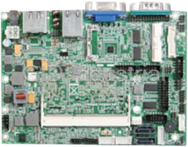
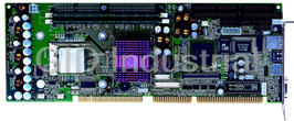
The ROBO-6600VL-A is a half-size tualatin Pentium III/Celeron PIC Single Board Computer. Targeting on
the rapid growing networking, and telecommunication markets, the ROBO-6600VL-A is designed with
Intel Dynamic Video memory technology, and Dual-10/100M Base-TX Ethernet chips. This makes the
ROBO-6600VL-A a perfect solution for not only popular Networking Applications like Firewall, Gateway, and
e-Server, but also for CTI (Computer Telephony Integration) equipments such as PBX, Digital Logger, etc.
It accommodates up to 512MB SDRAM for demanding applications. Its 6-layer printed circuit board
combining with noise-tolerant and low power consumption CMOS technology enables the ROBO-6600VL-A
to withstand any harsh industrial environments very well.
The ROBO-6600VL-A SBC comes with hardware monitoring that monitors system and CPU temperature,
system voltages, fans Speed and CPU and chassis fan speeds to prevent unexpected system failures by
warning the user of adverse conditions. The power management feature provides power savings by
slowing down the CPU clock, turning off the monitor screen and stopping the HDD spindle motor to
conserve energy. If the system stays idle for certain period of time
Other standard specification include two serial ports (one RS-232 and one RS- 232/422/485 selectable), one
multi-mode (ECP/EPP/SPP) parallel port, one floppy drive controller, and one PS/2 keyboard / mouse
interface. The built -in PCI Enhanced IDE controller supports up to four IDE devices and Ultra ATA /
100/66/33 bus master modes.
For other more simple application, there are B version with one LAN.
1.2 Features
l PCI Bus
l Support Intel Tualatin CPU up to 1.26GHz
l On-board dual Intel 100/100BASE-TX Ethernet controllers
l Built-in AGP VGA, shared system memory up to 4MB
l Built-in Sound function
User’s Manual
1
Chapter1 Introduction
1.3 Specification
ROBO-6600VL-A
Processor : IntelÒ Tualatin/Coppermine Pentium III / CeleronÔ Processor in
Socket 370
Chipset : IntelÒ 815E chipset
System Memory : One DIMM socket, support up to 512MB SDRAM
BIOS : AMIÒ BIOS
Graphics Controller : Internal graphic controller with Intel’s Dynamic Video Memory
Technology, resolution up to 1600 x 1200 x 256 colors @ 85 Hz, with
VGA connector
Ethernet Controller : Intel 82562ET and Intel 82559 chip, support Dual-10/100M Base-T
Ethernet, Wake On LAN, supported via ATX power supply
IDE Drive Interface : Two PCI IDE port that support up to Four IDE devices and Ultra
ATA/100/66/33
Floppy Drive Interface : One FDD port, support up to two floppy devices
Serial Port Two COM ports, one RS-232 and one RS-232/422/485
Audio/Sound : AC 97 2.0 Codec, CD-in header on-board
Parallel Port : One multi-mode parallel port ( SPP / EPP / ECP )
Bus Interface : PCI bus ( Rev. 2.2 compatible) Interface
RTC : Internal RTC with Li battery
Keyboard/Mouse Connector : 6-pin mini-Din PS/2 keyboard/mouse connector and 5-pin keyboard
header
Watchdog Timer : 64-level time-out intervals
Universal Serial Bus : Support 4 USB (Rev. 1.1) ports
Power Connector : 4-Pin AT Power Connector & 4-Pin ATX function Pin Header
Health Monitoring : Enhanced hardware monitor functions
Operating Temperature : 0 °C~60 °C
Storage Temperature : -10 °C~70 °C
Humidity : 5 %~95% RH, noncondensing
Dimensions : 185 x 122 mm ± 0.5 mm
Options : 4port USB Cable Kit
User’s Manual
2
Chapter1 Introduction
1.4 Unpack your ROBO-6600VL-A and Accessory
Before you begin to install your card, please make sure that you received the following materials as listed
below:
l ROBO-6600VL-A SBC x 1 pc Single Board Computer
l Keyboard and Mouse Cable x 1 pc 6pin Mini-Din PS/2 connector to 6pin PS/2 K/B+6pin PS/2
Mouse Cable
l LPT/COM cable x 1 pc 26-pin to 25-pin with 10-pin to 9-pin D-Sub Cable
l ATX Feature Cable x 1 pc 4-pin 40cm cable
l IDE Cable x 1 pc DMA-66 80pin IDE Cable
l FDD Cable x 1 pc 34 to 34-pin Standard Header Flat Ribbon Cable
l Utility CD-ROM x 1 pc Drivers, Manual & Utilities
User’s Manual
3
122
122
117.5
117.5
4.5
3.51
.03
0
Chapter1 Introduction
1.5 Board Layout
0
0
4.47
16
180.49 180.49
185
184.97
User’s Manual
4
Chapter2 Installation
Chapter 2 . Installation
2.1 Hardware Setup and Installation
2.1.1 CPU Installation and Upgrading
CPU
Step 1 Locate the ZIF socket and open it by first pulling the lever of socket upward.
Step 2 Insert the CPU into the socket. Please keep the lever right angle when inserting CPU.
User’s Manual
5
Chapter2 Installation
Step 3 When inserting the CPU please note the correct orientation as shown. The notched corner
should point toward the end of the lever.
Step 4 Push the lever down to close the socket.
Step 5 Attach the heatsink onto the CPU.
Step 6 Push the clip of heatsink downward to hock the ear of socket firmly.
Step 7 Finally attach the fan cable to the CPU fan header.
User’s Manual
6
Chapter2 Installation
2.1.2 System Memory Installation
Step 1 Open latches of DIMM socket.
Step 2 Insert the RAM module into the DIMM socket.
Step 3 Press the latches into the notches of the RAM module.
User’s Manual
7
FDCA1
LPTA1 IDEB1
DIM1
Chapter2 Installation
2.2 Jumper Settings and Connectors
2.2.1 Board Outline of ROBO-6600VL-A
5 1
COMA1
PKM1 VGAA1 LANE1
SC2T2
2
6
1 9
SC2T1
KCN1
1
2
1
KBPW1
12
4
3
COMB1
5 1
LN1
9 SM1
1 1
2
9
10
15
1
JP5
1
2
2
16
10 2
PSW1
JP3
1 1
1
2
2
IRDA1
5
CPU CPU
26
2
FAN1
34
3
2
1
1
CMOS1
3 1
4PSM1
4
1
USBA2
USBA1
JP4
ATXC1 9 1 9 1
40
3 1 4
1
PLRS1
IDEB2
11
1
User’s Manual
8
Chapter2 Installation
2.2.2 Jumper Setting Summary of ROBO-6600VL-A
Location Function
JP4 For AT & ATX Function
KBPW1 For Keyboard Voltage
JP3 For 82562ET LAN Function
JP5 For 82559 LAN Function
SC2T1 / SC2T2 Select COM2 Type
CMOS1 Clear CMOS
l JP4:For AT&ATX Function
JP4 Description
1-2 VCC Default AT Function
2-3 STB5V ATX Function
Defualt:(1-2)
CPU
JP4
3 1
JP4
l KBPW1: For Keyboard Voltage
KBPW1 Description
KBPW1
1-2 VCC
2-3 5VSB
CPU
KBPW1
1
Default:(1-2)
3
User’s Manual
9
Chapter2 Installation
l JP3:For 82562ET LAN Function
JP3 Description
OFF Enabled
ON Disabled
JP3
JP3
1
2
CPU
l JP5:For 82559 LAN Function
JP5 Description
OFF Enabled
ON Disabled
JP5
JP5
1
2
CPU
User’s Manual
10
Chapter2 Installation
l SC2T1/SC2T2: Select COM2 Type
COM2 Type SC2T2 SC2T1
RS-232 (Default) 1-5,2-6,3-7,4-8 1-2
RS-422 5-9,6-10,7-11,8-12 3-4
RS-485 5-9,6-10,7-11,8-12 5-6
SC2T1
SC2T2
CPU
SC2T2
SC2T1
1
9
5
1
2
6
12
4
l CMOS1:Clear CMOS
Description CMOS1
Normal (Default) 1-2
CLEAR CMOS 2-3
CMOS1 CPU
3 1
CMOS1
Note: If you forget your password, the only
way to solve this problem is to discharge the
CMOS memory by turning power off and
placing a shunt on the CMOS1 (2-3) for 5
seconds, then removing the shunt.
User’s Manual
11
Chapter2 Installation
2.2.3 I/O Connector Summary
Connector Function
ATXC1 ATX Power Expansion (Header)
PLRS1 Connector for Power LED, Reset, Speaker Connector, HD LED
IRDA1 Consumer Remote Control IR (CIR)
PSW1 ATX Power ON Switch (Header)
4PSM1 Power Connector
USBA1 USB Port#1 Connector
USBA2 USB Port#2 Connector
VGAA1 VGA Connector
LPTA1 Parallel Port Connector (Header)
IDEB1/2 IDE Interface Connector
PKM1 PS/2 Keyboard & Mouse Connector (Mini Din)
FAN1 FAN Connector
KCN1 5pin Keyboard Cable Connector
COMA1 RS-232 Serial Port#1 Connector (D-Sub)
COMB1 Serial Port#2 Connector (Header)
FDCA1 Floppy Interface Connector (Header)
LANE1 LAN Connector
LN1 LAN Header
SM1 Sound & Mouse Header
l ATXC1: ATX Power Expansion Header
Pin No. Description
1 Ground
2 5V Standby
3 Ground
4 Power ON
ATXC1
4
1
CPU
Note: To have full features from ATX power, the
ATXC1 should be wired to the connectors with the
same function on the Backplane. Please refer to the
connector definition and description for more
information.
ATXC1
User’s Manual
12
Chapter2 Installation
l PLRS1 : Power LED,HD LED,Reset, Speaker Connector
Pin No. Description
1 Power LED +
2 Power LED +
3 GND
4 HDD LED +
5 HDD LED -
6 RESET SW +
7 RESET SW – (GND)
8 External Speaker -
9 Internal Buzzer -
CPU
10 NC
11 External Speaker +
Default: 8-9(ON) Internal Buzzer
PLRS1
1
11
PLRS1
l IRDA1: Consumer Remote Control IR (CIR)
Pin No. Description
1 +5V
2 NC
3 CIRRX
4 Ground
5 CIRTX
IRDA1
CPU
IRDA1
1
5
User’s Manual
13
Chapter2 Installation
l PSW1: ATX Power ON Switch (Header)
Pin No. Description
1 SWON-
2 Ground
PSW1
PSW1 CPU
1
2
l 4PSM1 : 4 Pin Power Connector ( Big-4P Male )
Pin No. Description
1 +12V
2 Ground
3 Ground
4 +5V
4PSM1
CPU
4
1
4PSM1
User’s Manual
14
Chapter2 Installation
l USBA1:USB Port #1 Connector
Pin No. Description Pin No. Description
1 USB_VCC 2 USB_VCC
3 USB D0- 4 USB D1-
5 USB D0+ 6 USB D1+
7 Ground 8 Ground
9 USB Port#1Ground 10 USB Port#1 Ground
USBA1
1
9
CPU
2
10
USBA1
l USBA2:USB Port #2 Connector 2x5 Pin 2.54mm
Pin No. Description Pin No. Description
1 USB_VCC 2 USB_VCC
3 USB D2- 4 USB D3-
5 USB D2+ 6 USB D3+
7 Ground 8 Ground
9 USB Port#2Ground 10 USB Port#2 Ground
USBA2
1
9
2
10
CPU
USBA2
User’s Manual
15
Chapter2 Installation
l VGAA1 : External VGA Connector ( 15 Pin D-Sub )
Pin No. Description
1 Red Color Signal
2 Green Color Signal
Blue Color Signal
3
VGAA1
4 NC
5 Ground
6 Ground
7 Ground
8 Ground
CPU
9 NC
10 Ground
11 NC
12 DDC-DATA
13 H-Sync.
14 V-Sync.
15 DDC-CLK
5 1
10 6
15 11
VGAA1
User’s Manual
16
Chapter2 Installation
l IDEB1/ IDEB2 : IDE Interface Connector
Pin No. Description Pin No. Description
1 Reset # 2 Ground
3 Data 7 4 Data 8
5 Data 6 6 Data 9
7 Data 5 8 Data 10
9 Data 4 10 Data 11
11 Data 3 12 Data 12
13 Data 2 14 Data 13
15 Data 1 16 Data 14
17 Data 0 18 Data 15
19 Ground 20 NC
21 DMA REQ# 22 Ground
23 IOW # 24 Ground
25 IOR # 26 Ground
27 IOCHRDY 28 Ground
29 DMA ACK # 30 Ground
31 Interrupt 32 NC
33 SA1 34 PD80P / SD80P
35 SA0 36 SA2
37 HDC CS0 # 38 HDC CS1 #
39 HDD Active LED # 40 Ground
IDEB1/2
1 2
CPU
IDEB2 IDEB1
39 40
User’s Manual
18
Chapter2 Installation
l KCN1: Keyboard Cable Connector
Pin No. Description
1 Keyboard Clock
2 Keyboard Data
3 NC
4 Ground
5 +5V
KCN1
KCN1
CPU
5 1
l COMA1 : RS-232 Serial Port #1 Connector ( D-Sub )
Pin No. Description
1 Data Carrier Detect ( DCDA # )
2 Receive Data ( RXDA )
3 Transmit Data ( TXDA )
4 Data Terminal Ready ( DTRA # )
5 Ground ( GND )
6 Data Set Ready ( DSRA # )
7 Request To Send ( RTSA # )
8 Clear To Send ( CTSA # )
9 Ring Indicator ( RIA # )
COMA1
COMA1
1 5
CPU
6 9
User’s Manual
20
Chapter2 Installation
l COMB1 : Serial Port #2 Connector ( Header )
Description
Pin No.
RS-232 RS-422 RS-485
1 Data Carrier Detect (DCDB #) Transmit Data– (TXD-) Data -
2 Data Set Ready (DSRB #) NC NC
3 Receive Data (RXDB) Transmit Data+ (TXD+) Data +
4 Request To Send (RTSB #) NC NC
5 Transmit Data (TXDB) Receive Data+ (RXD+) NC
6 Clear To Send (CTSB #) NC NC
7 Data Terminal Ready (DTRB #) Receive Data- (RXD-) NC
8 Ring Indicator (RIB #) NC NC
9 Ground NC NC
10 NC NC NC
COMB1
COMB1
1 2
10
9 CPU
User’s Manual 21
Chapter2 Installation
l FDCA1 : Floppy Interface Connector
Pin No. Description Pin No. Description
1 Ground 2 Density Select
3 Ground 4 NC
5 Ground 6 DS1
7 Ground 8 Index #
9 Ground 10 Motor Enable A #
11 Ground 12 Drive Select B #
13 Ground 14 Drive Select A #
15 Ground 16 Motor Enable B #
17 Ground 18 Direction #
19 Ground 20 Step #
21 Ground 22 Write Data #
23 Ground 24 Write Gate #
25 Ground 26 Track 0 #
27 Ground 28 Write Protect #
29 NC 30 Read Data #
31 Ground 32 Head Side Select #
33 NC 34 Disk Change #
FDCA1
1 2
CPU
FDCA1
34
33
User’s Manual
22
Chapter2 Installation
l SM1:Sound/Mouse (Female)
Pin No. Description Pin No. Description
1 ICH_SPKR 2 AC97
3 AC_RST- 4 VCC
5 SYNC 6 GND
7 SDIN0 8 +3.3V
9 NC 10 GND
11 BITCLK 12 +5V STANDBY
13 SDOUT 14 NC
15 MSDAT 16 MSCLK
SM1
SM1
15
1
16
2
CPU
l IAC-SML1 Installation
Insert IAC-SML1 into the SM1 and LN1 header.
User’s Manual
24
Chapter2 Installation
Chapter 3 BIOS Setup
The AMI‘s ROM BIOS provides a built-in Setup program that allows user to modify the basic system
configuration and settings. The modified data will be stored in a battery-backed CMOS RAM so that these data
will be retained even when the power is turned off. In general, the information saved in the CMOS RAM stay
unchanged unless there is configuration change in the system, such as hard drive replacement or new
equipment is installed. AMI is a registered trademark of the American Megatrends, Inc.
3.1 Running AMI BIOS
The Setup Utility is stored in the BIOS ROM. When the power of the computer system is turned on, a screen
message appears to give you an opportunity to call up the Setup Utility; while the BIOS will enter the Power
On Self Test (POST) routines. The POST routines perform various diagnostic checks while initializing the
board hardware. If the routines encounter an error during the tests, the error will be reported in either of
the two different ways – (1) hear a series of short beeps, or (2) see an error message on the screen display.
There are two kinds of error: fatal or non-fatal. The system can usually continue to boot up sequence with
the non-fatal errors. Non-fatal error messages usually appear on the screen along with the following
instructions:
“ Press to RESUME ”
Write down the message and press the F1 key to continue the bootup sequence. After the POST routines
are completed, the following message appears:
“ Press DEL to enter SETUP ”
Entering Setup
Turn on the power of the computer system and press immediately. If you don’t have the chance to
respond, reset the system by simultaneously typing the , and keys, or by pushing the
‘ Reset ’ button on the system cabinet. You can also restart by turning the system OFF then ON.
Note: BIOS versions are regularly updated form time to time without notices. Therefore, the options available
in your setup screen may differ from the options shown in this manual.
User’s Manual 25
Chapter2 Installation
3.2 AMI BIOS HIFLEX Setup Utility
To access the AMI BIOS HIFLEX SETUP UTILITY program, press the key. The screen display will
appears as:
Main Program Screen
AMIBIOS HIFLEX SETUP UTILITY
© 2001 American Megatrends, Inc. All Rights Reserved
IAC-H669 Ver.A 2002-06-26
Standard CMOS Setup
Advanced CMOS Setup
Advanced Chipset Setup
Power Management Setup
PCI / Plug and Play Setup
Peripheral Setup
Hardware Monitor Setup
Auto-Detect Hard Disks
Change User Password
Change Supervisor Password
Auto Configuration with Optimal Settings
Auto Configuration with Fail Safe Settings
Save Settings and Exit
Exit Without Saving
Standard CMOS setup for changing time, date, hard disk type, etc.
ESC : Exit ¯ : Sel F2/F3 : Color F10 : Save & Exit
This screen provides access to the utility‘s various functions.
Listed below are the explanation of the keys displayed at the bottom of the screen:
: Exit the utility.
á â : Use arrow keys á â to move cursor to your desired selection.
/ : Changes background and foreground colors.
: Saves all changes made to Setup and exits program.
Standard CMOS Setup : Use this menu for basic system configurations, such as time, date, etc.
Advanced CMOS Setup: Use this menu to specify your settings for Advance CMOS.
Advanced Chipset Setup: Use this menu to change the values in the chipset registers and optimize your
system’s performance.
Power Management Setup: Use this menu to specify your settings for power management.
PCI / Plug and Play Setup: Use this menu to specify your settings for PCI/Plug and Play.
Peripheral Setup: Use this menu to specify your settings for integrated peripherals.
Hardware Monitor Setup: This entry shows your PC’s current status, and allows you to adjust CPU clock,
core voltage, etc.
Auto-Detect Hard Disks: Use this menu to automatically detect the characteristics of most hard drives.
Change User Password: Use this menu to set User Password.
User’s Manual
26
Chapter2 Installation
Change Supervisor Password: Use this menu to set Supervisor Password.
Auto Configuration with Optimal Settings: This option allows you to load the default values to your
system configuration. These default settings are optimal and enable all high performance features.
Auto Configuration with Fail Safe Settings: This option allows you to load the troubleshooting default
values permanently stored in the BIOS ROM. These default settings are non-optimal and disable all
high-performance features.
Save Settings and Exit: Save changes to CMOS and exit setup.
Exit Without Saving: Abandon all changes and exit setup.
User’s Manual 27
Chapter2 Installation
3.3 Standard CMOS Setup
When you select the “STANDARD CMOS SETUP” on the main program, the screen display will appears as:
Standard CMOS Setup Screen
AMIBIOS SETUP – STANDARD CMOS SETUP
© 2001 American Megatrends, Inc. All Rights Reserved
Date (mm/dd/yyyy)
: Tue Apr 04, 2002 Base Memory : 639KB
Time (hh/mm/ss) : 11:02:56 Extd Memory : 510MB
1
Floppy Drive A : 1.44 MB 3 /
2
Floppy Drive B : Not Installed
LBA Blk PIO 32 Bit
Type Size Cyln Head WPcom Sec Mode Mode Mode Mode
Pri Master : Auto On
Pri Slave : Auto On
Pri Master : Auto On
Pri Slave : Auto On
Boot Sector Virus Protection Disabled
ESC:Exit ¯ : Sel
Month : Jan - Dec
Day : 01 - 31 PgUp/PgDn: Modify
Year : 1980 - 2099 F1: Help F2/F3:Color
Standard CMOS Setup options are displayed by choosing the Standard field from the AMIBIOS HIFLEX SETUP
menu. All Standard Setup options are described below.
Date: This allows you to set the system to the date that you want (usually the current date). The format is
.
Day Day of the week, from Sun to Sat, determined by BIOS. Real-only.
Month The month from Jan. through Dec.
Date The date from 1 to 31 can be keyed by numeric function keys.
Year The year can be adjusted by users.
Time: This allows you to set the system time that you want (usually the current time). The time format is
.
Pri Master/ Pri Slave: Press PgUp/<+> or PgDn/<-> to select the hard disk drive type. The specification of
hard disk drive will show up on the right hand according to your selection.
Type Type of the device.
Size Capacity of the device.
Cyln Number of cylinders.
Head Number of heads.
Wpcom Write precompensation cylinder.
Sec Number of sectors.
Mode Access mode.
Floppy Drive A, B : Choose the Floppy Drive A or B field to specify the floppy drive type. The settings are
1 1 1 1 1
360 KB 5 / ”, 1.2 MB 5 / ”, 720 KB 3 / ”, 1.44 MB 3 / ”, or 2.88 MB 3 / ”.
4 4 2 2 2
Boot Sector Virus Protection: The item is to set the Virus Warning feature for IDE Hard Disk boot sector
protection. When Enabled, BIOS will issue a virus warning message and beep if a write to the boot sector or
the partition table of the HDD is attempted. Setting options: Disabled and Enabled.
Note: This feature only protects the boot sector, not the whole hard disk.
User’s Manual
28
Chapter2 Installation
3.4 Advanced CMOS Setup
When you select the “ADVANCED CMOS SETUP” on the main program, the screen display will appears as:
Advanced CMOS Setup Screen
AMIBIOS SETUP – ADVANCED CMOS SETUP
©2001 American Megatrends, Inc. All Rights Reserved
Quick Boot Enabled
1st Boot Device FLOPPY
2nd Boot Device IDE-0
3rd Boot Device Disabled
Try Other Boot Devices Yes
Initial Display Mode BIOS
Display Mode at Add-On ROM Init Force BIOS
Floppy Access Control Read-Write
S.M.A.R.T. for Hard Disks Enabled
BootUp Num-Lock On
Floppy Drive Seek Disabled
PS/2 Mouse Support Enabled
Primary Display VGA/EGA
Password Check Setup
L1 Cache WriteBack
L2 Cache WriteBack
System BIOS Cacheable Enabled
C000, 16K Shadow Enabled
C400, 16K Shadow Enabled
C800, 16K Shadow Enabled
CC00, 16K Shadow Disabled
D000, 16K Shadow Disabled
¯ : Sel
D400, 16K Shadow Disabled ESC : Exit
D800, 16K Shadow Disabled PgUp/PgDn : Modify
DC00, 16K Shadow Disabled F1: Help F2/F3: Color
Note : The above page of the Advanced CMOS Setup only shows part of the related options. To proceed
to the next options, please move your cursor downwards.
Advanced Setup options are displayed by choosing the Advanced icon from the WINBIOS Setup main menu.
All Advanced Setup options are described in this section.
Quick Boot: Setting the item to “Enabled” allows the system to boot within 5 seconds by skipping some
check items. Settings: Enabled and Disabled.
User’s Manual 29
Chapter2 Installation
st nd rd
1 /2 /3 Boot Device: The items allow you to set the sequence of boot devices where AMIBIOS attempts
to load the operation system. Possible settings are:
IDE-0 The system will boot from the first HDD.
IDE-1 The system will boot from the second HDD.
IDE-2 The system will boot from the third HDD.
IDE-3 The system will boot from the fourth HDD.
Floppy The system will boot from floppy drive.
ARMD-FDD The system will boot from any ARMD device, such as LS-120 or ZIP
drive, that functions as a floppy drive.
ARMD-HDD The system will boot from ARMD device, such as MO or ZIP drive, that
functions as hard disk drive.
CDROM The system will boot from the CD-ROM.
SCSI The system will boot from the SCSI.
NETWORK The system will boot from the Network drive.
BBS-0 The system will boot from the first BBS (BIOS Boot Specification)
compliant device.
BBS-1 The system will boot from the second BBS (BIOS Boot Specification)
compliant device.
BBS-2 The system will boot from the third BBS (BIOS Boot Specification)
compliant device.
BBS-3 The system will boot from the fourth BBS (BIOS Boot Specification)
compliant device.
Disabled Disable this sequence.
st nd rd
Note: Available settings for “1 /2 /3 Boot Device “ vary depending on the bootable devices you have
installed. For example, if you did not install a floppy drive, the setting” Floppy” does not show up.
Try Other Boot Devices : Setting the option to yes allows the system to try to boot from other devices if the
st nd rd
system fails to boot from the 1 /2 /3 Boot Device.
Initial Display Mode: Set this option to Silent to enable the AMIBIOS SilentBoot feature. This option
specifies the initial display mode when the system boots. The settings are:
Setting Description
BIOS The standard BIOS boot messages displayed before booting the system will
appear on the system monitor.
Silent The standard messages will not appear on the system monitor and the
system will boot to the operating system immediately. Only BIOS error
messages will appear.
Display Mode at Add-On ROM Init: This option specifies the system display mode that is set at the time
that AMIBIOS POST initializes an optional adapter ROM. The settings are:
Setting Description
Force BIOS The display mode currently being used by AMIBIOS is used.
Keep Current The current display mode is used.
Floppy Access Control: This option specifies the read/write access that is set when booting from a floppy
drive. The settings are Read/Write or Read-Only. The Optimal and Fail-Safe default settings are Read/Write.
S.M.A.R.T. for Hard Disks : This allows you to activate the S.M.A.R.T. (Self-Monitoring Analysis & Reporting
Technology) capability for the hard disks. S.M.A.R.T is a utility that monitors your disk status to predict hard
disk failure. This gives you an opportunity to move data to a safe place before the hard disk becomes offline.
Settings: Enabled and Disabled.
BootUp Num-Lock : Set this option to Off to turn the Num Lock key off when the computer is booted so you
can use the arrow keys on both the numeric keypad and the keyboard. The settings are On or Off. The
default setting is On.
Floppy Drive Seek : Set this option to Enabled to specify that floppy drive A: will perform a Seek operation
at system boot. The settings are Disabled or Enabled. The Optimal and Fail-safe default settings are
Disabled.
User’s Manual
30
Chapter2 Installation
PS/2 Mouse Support : When this option is set Enabled, AMIBIOS supports a PS/2 type mouse. The
settings are Enabled or Disabled. The default setting is Disabled. System Boot Up Sequence.
Primary Display : This option specifies the type of display monitor and adapter in the computer. The
settings are Mono, CGA40, CGA80, EGA/VGA or Absent. The Optimal and Fail-Safe default settings are
EGA/VGA.
Password Check : This option enables password checking every time the computer is powered on or every
time WINBIOS Setup is executed. If Always is chosen, a user password prompt appears every time the
computer is turned on. If Setup is chosen, the password prompt appears if WINBIOS is executed. The
Optimal and Power-On defaults are Setup.
L1 Cache: The option enabled or disabled the internal cache memory in the processor.
L2 Cache: The option enables secondary cache memory. If enabled is selected, external cache memory is
enabled. If disabled is selected, external cache memory is disabled.
System BIOS Cacheable : When this option is set to Enabled, the contents of the F0000h system memory
segment can be read from or written to L2 secondary cache memory. The contents of the F0000h memory
segment are always copied from the BIOS ROM to system RAM for faster execution.
The settings are Enabled or Disabled. The Optimal default setting is Enabled. The Fail-Safe default setting is
Disabled.
C000,16K Shadow D000,16K Shadow
C400,16K Shadow D400,16K Shadow
C800,16K Shadow D800,16K Shadow
CC00,16K Shadow DC00,16K Shadow
These options control the location of the contents of the 16KB of ROM beginning at the specified memory
location. If no adaptor ROM is using the named ROM area, this area is made available to the local bus. The
settings are:
Setting Description
Shadow The contents of C0000h - C3FFFh are written to the same address in
System memory (RAM) for faster execution.
Cache The contents of the named ROM area are written to the same address in
system memory (RAM) for faster execution, if an adaptor ROM will be
using the named ROM area. Also, the contents of the RAM area can be
read from and written to cache memory.
Disabled The video ROM is not copied to RAM. The contents of the video ROM
cannot be read from or written to cache memory.
The default setting is Cache.
In the AMIBIOS for the Intel Triton chipset, the E000h page is used as ROM during POST, but shadowing is
disabled and the ROM CS# signal is disabled to make the E000h page available on the local bus.
User’s Manual 31
Chapter2 Installation
3.5 Advanced Chipset Setup
When you select the “ADVANCED CHIPSET SETUP” on the main program, the screen display will appears as:
Advanced Chipset Setup Screen
AMIBIOS SETUP – ADVANCED CHIPSET SETUP
© 2001 American Megatrends, Inc. All Rights Reserved
CPU BIST Enable Disabled
ICH Delayed Transaction Enabled
DMA Collection Buffer Enable Disabled
DRAM Page Closing Policy Open
Memory Hole Disabled
ClkGen Spread Spectrum Disabled
System memory Frequency Auto
SDRAM Timing by SPD Enabled
DRAM Refresh 15.6 uS
DRAM Cycle time (SCLKs) 7/9
CAS# Latency (SCLKs) 3
RAS to CAS delay (SCLKs) 3
SDRAM RAS# Precharge (SCLKs) 3
Internal Graphics Mode Select 1 MB
Display Cache Window Size 64 MB
AGP Aperture Window 64 MB
Initialize Display Cache Memory Enabled
Paging Mode Control Closed
RAS-to-CAS Default
CAS Latency Slow
RAS Timing Slow
RAS Precharge Timing Slow
CPU Latency Timer Disabled
USB Function Disabled
USB Device Legacy Support Disabled
Port 64/60 Emulation Disabled
¯ : Sel
ESC : Exit
PgUp/PgDn : Modify
F1:Help F2/F3 : Color
In the ‘Advanced Chipset Setup’ page, all options are predefined by the system board designer. Any attempt
to change the parameter of the fields are not recommended.
ICH Delayed Transaction: The ICH was designed to provide high performance support to PCI peripherals
using its data prefetch capabilities. If a PCI master is burst reading and is disconnected by the ICH to prefetch
the requested cache line, the ICH will Delay Transaction the cycle while it prefetches more data, and gire the
bus to another agent.
DMA Collection Buffer Enable: Enable RMA Collection Buffer for LPC I/F and PC/PCI DMA. Settings are
Disabled and Enabled.
DRAM Page Closing Policy: If this setting is open, GMCH will tend to leave the DRAM pages open. Settings
are Open and Closed.
Memory Hole: This option allows the end user to specify the location of a memory hole for memory space
requirement from ISA-bus cards.
ClkGen Spread Spectrum: This is to enable or disable Clock Generator’s Spread Spectrum function, when
overclocking the processor, always set it to Disabled.
User’s Manual
32
Chapter2 Installation
SDRAM Timing by SPD: Selects whether DRAM timing is controlled by the SPD (Serial Presence Detect)
EEPROM on the DRAM module. Setting to SPD enables CAS# Latency. RAS# Precharge, RAS# to CAS# Delay
and Precharge Delay automatically to be determined by BIOS based on the configurations on the SPD.
Selecting Manual allows users to configure these fields manually.
DRAM Refresh: This option specifies the refresh rate frequency for the installed system memory SDRAM
DIMMs. If you have good quality of DRAM, you can choose longer refresh rate to get better system
performance.
DRAM Cycle time (SCLKs): Select the number of SCLKs for an access cycle. The setting are:5/7 and 7/9.
CAS# Latency (SCLKs): This controls the timing delay (in clock cycles) before SDRAM starts a read
command after receiving it. Settings are 3 Clocks and 2 Clocks. 2 Clocks increases the system performance
while 3 Clocks provides more stable performance.
SDRAM RAS# to CAS# Delay (SCLKs): This field allows you to set the number of cycles for a timing delay
between the CAS ans RAS strobe signals, used when DRAM is written to , read from or refreshed. Fast speed
offers faster performance while slow speed offers more stable performance. Settings: 3 Clocks and 2 Clocks.
SDRAM RAS# Precharge (SCLKs): The field specifies the idle cycles before precharging an idle bank.
Settings: 7 Clocks, 6 Clocks and 5 Clocks.
Internal Graphics Mode Select: This setting allows the Internal Graphics mode to be modified. The
Optimal and Fail-Safe default settings are Enabled, 1MB.
Option Description
Enabled, 1MB This option allows the Internal Graphic controller to allocate 1MB of system
memory for video display use. This is the default setting.
Enabled, 512KB This option allows the Internal Graphic controller to allocate 512KB of
system memory for video display use.
Disabled This option allocates no system memory for video display use.
Display Cache Window Size: This setting allows the Display Cache Window Size to be modified. The
Optimal and Fail-Safe default settings are 64MB.
Option Description
32MB This option allows caching of up to 32MB.
64MB This option allows caching of up to 64MB. This is the default setting.
AGP Aperture Window: The field selects the size of the Accelerated Graphics Port( AGP) a perture. Aperture
is a portion of the PCI memory address range dedicated for graphics memory address space. Host cycles that
hit the aperture range are forwarded to the AGP without any translation. Settings are 4MB, 8MB, 16MB, 32MB,
64MB, 128MB and 256MB.
Local memory Frequency: This item allows you to select the Memory Frequency.
Initialize Display Cache Memory: This option will enable or disable Local Memory (Display Cache) and
UMA capable. Settings are Enabled and Disabled.
Paging Mode Control: Display cache paging mode. Settings are Open and Closed.
RAS-to-CAS: This field allows you to set the number of cycles for a timing delay between the CAS and RAS
strobe signals, used when DRAM is written to , read from or refreshed. Fast speed offers faster performance
while slow speed offers more stable performance.
CAS Latency: This controls the timing delay before SDRAM starts a read command after receiving it.
RAS Timing: This item controls the timing for RAS. Settings are Fast and Slow.
User’s Manual 33
Chapter2 Installation
RAS Precharge Timing: This item controls the number of cycles for RAS to be allowed to precharge.
Settings are Fast and Slow.
CPU Latency Timer: During Enabled, A deferrable CPU cycle will only be Deferred after it has been in a
Snoop Stall for 31 clocks and another ADS# has arrived. During Disabled, A deferrable CPU cycle will be
Deferred immediately after the GMCH receives another ADS#.
USB Function: This option will enable on-chip USB function to support USB (Universal Serial Bus) peripheral
devices if user chooses the “Enabled” setting.
USB Device Legacy Support: This field supports Universal Serial Bus (USB) devices. If detected, USB
controller legacy mode will be enabled. If not detected, USB controller legacy mode will be disabled.
Port 64/60 Emulation: Setting this option to allow a USB keyboard to act like a legally keyboard.
User’s Manual
34
Chapter2 Installation
3.6 Power Management Setup
The “Power Management Setup” controls the CPU card‘s “Green” features. When you select the “POWER
MANAGEMENT SETUP” on the main program, the screen display will appears as:
Power Management Setup Screen
AMIBIOS SETUP – POWER MANAGEMENT SETUP
© 2001 American Megatrends, Inc. All Rights Reserved
ACPI Function Disabled
Power Management /APM Enabled
Video Power Down Mode Stand By
Hard Disk Power Down Mode Stand By
Standby Time Out Disabled
Keyboard & PS/2 Mouse Monitor
FDC / LPT/ COM Ports Monitor
Primary Master IDE Monitor
Primary Slave IDE Ignore
Secondary Master IDE Monitor
Secondary Slave IDE Ignore
Power Button Function On/Off
Restore on AC/ Power Loss Power On
Wake Up On PME/Lan Enabled
Resume By Alarm Disabled
Alarm Date 15
¯ : Sel
Alarm Hour 12 ESC : Exit
Alarm Minute 30 PgUp/PgDn : Modify
Alarm Second 30 F1:Help F2/F3 : Color
Power Management Setup options are displayed by choosing the Power Management field from the WINBIOS
Setup main menu. All Power Management Setup options are described in this section.
ACPI Function: This item is to activate the ACPI (Advanced Configuration and Power Management Interface)
Function. If your operating system is ACPI-aware, such as Windows 98SE/2000/ME, select Yes. Settings: Yes
and No.
Power Management /APM: Setting to Enabled will activate the Advanced Power Management (APM)
feature to enhance power saving modes. Settings: Enabled and Disabled.
Video Power Down Mode: This option specifies the power conserving state that the VESA VGA video
subsystem enters after the specifies period of display inactivity has expired.
Hard Disk Power Down Mode: This option specifies the power conserving state that the hard disk drive
enters after the specified period of hard drive inactivity has expired. The setting are Standby, or Suspend.
Standby Time Out: This option specifies the length of the period of system inactivity while the computer is
in Full-On power state before the computer is placed in Standby mode. When this length of the time expires,
the computer enters Standby Timeout state. In Standby mode, some power use is curtailed.
Keyboard & PS/2 Mouse: The item controls keyboard and PS/2 mouse to power on the system. Settings
are Monitor and Ignore.
FDC / LPT/ COM Ports, Primary Master IDE, Primary Slave IDE: These items specify if the BIOS will
monitor the activity of the listed hardware peripheral or component. If set to Monitor, any activity detected on
the specified hardware peripheral or component will wake up the system or prevent the system from entering
the power saving modes. Settings: Monitor and Ignore.
Primary Master IDE: The item controls Primary Master IDE to power on the system. Settings are Monitor
and Ignore.
User’s Manual 35
Chapter2 Installation
Primary Slave IDE: The item controls Primary Slave IDE to power on the system. Settings are Monitor and
Ignore.
Secondary Master IDE: The item controls Secondary Master IDE to power on the system. Settings are
Monitor and Ignore.
Secondary Slave IDE: The item controls Secondary Slave IDE to power on the system. Settings are Monitor
and Ignore.
Power Button Function: This feature sets the function of the power button. Settings:
On/Off The power button functions as normal on/off button.
Suspend When you press the power button, the computer enters the suspend/sleep mode, but if
the button is pressed for more than four seconds, the computer is turned off.
Restore on AC/ Power Loss: This item specifies whether your system will reboot after a power failure.
Available options:
Power Off Leaves the computer in the power off before state.
Power On Reboots the computer.
Last State Restores the system to the previous status before the power failure.
Wake Up On PME/LAN: When setting to Enabled, this feature allow your system to be awakened from the
power saving modes through an incoming can from a signal from the LAN, or any event on PME(Power
Management Event). Settings: Enabled and Disabled.
Note: You need to install a LAN card supporting power on function for Resume On PME/ LAN function.
Resume By Alarm: This is used to enable or disable the feature of booting up the system on a schedule
time/ date. Settings: Enabled and Disabled.
Alarm Date/Hour/Minute/Second: If Resume On RTC Alarm is set to Enabled, the system will
automatically resume (boot up) on a specific date/hour/minute/second specified in these fields. Available
settings for each item are:
Alarm Date 01~31, Every Day
Alarm Hour 00~23
Alarm Minute 00~59
Alarm Second 00~59
User’s Manual
36
Chapter2 Installation
3.7 PCI Plug and Play Setup
Both the ISA and PCI buses on the CPU card use system IRQs & DMAs. You must set up the IRQ and DMA
assignments correctly through the PCI / Plug and Play Setup utility, otherwise the SBC will not work properly.
When you select the “PCI / PLUG AND PLAY SETUP” on the main program, the screen display will appears as:
PCI / Plug and Play Setup Screen
AMIBIOS SETUP – PCI / PLUG AND PLAY SETUP
© 2001 American Megatrends, Inc. All Rights Reserved
Plug and Play Aware O/S No
Reset Configuration Data No
PCI Latency Timer (PCI Clocks) 64
Primary Graphics Adapter External PCI
Allocate IRQ to PCI VGA Yes
DMA Channel 0 PnP
DMA Channel 1 PnP
DMA Channel 3 PnP
DMA Channel 5 PnP
DMA Channel 6 PnP
DMA Channel 7 PnP
IRQ3 ISA / EISA
IRQ4 ISA / EISA
IRQ5 PCI / PnP
IRQ7 ISA / EISA
IRQ9 PCI / PnP
IRQ10 PCI / PnP
IRQ11 PCI / PnP
¯ : Sel
IRQ14 PCI / PnP ESC : Exit
IRQ15 PCI / PnP PgUp/PgDn : Modify
F1: Help F2/F3 : Color
PCI/PnP Setup options are displayed by choosing the PCI/PnP Setup icon from the WINBIOS Setup main
menu. All PCI/PnP Setup options are described in this section.
Plug and Play Aware O/S: Set this option to “ Yes” if the operation system installed in the computer is Plug
and Play-aware. BIOS only detects and enables PnP ISA adapter cards that are required for system boot. The
Windows 95 operating system detects and enables all other PnP-aware adapter cards. Windows 95 is
PnP-aware. Set this option to “ No” if the operating system (such as DOS, OS/2, Windows 3.x) does not use
PnP.
Reset Configuration Data: This option allows the BIOS to rest the Configuration Data in the BIOS. The
Optimal and Fail-Safe default setting is No.
Option Description
No This setting preserves the PnP data. It does not force the PnP data to be
cleared on boot. This is the default setting.
Yes This option allows the PnP data to be rebuilt by the BIOS at every boot.
PCI Latency Timer (PCI Clocks): This option is used to control PCI latency timer period (follow PCI
clocks). Based on PCI specification 2.1 or later and PCI bus frequency in system, user can select different
timer to meet their PCI bus environment.
Primary Graphics Adapter: Initialize the PCI video display card on PCI slot before initializing any other
display device on the system. Thus the PCI slot display card becomes the primary display. Available options
are [PCI] and [AGP].
Allocate IRQ to PCI VGA: This option will be used to allocate IRQ for PCI VGA card. In general, some of
PCI VGA cards needs IRQ support.
User’s Manual 37
Chapter2 Installation
DMA Channel 0/1/3/5/6/7: These items specify the bus that the system DMA(Direct Memory Access)
channel is used. The settings determine if AMIBIOS should remove a DMA from the available DMAs passed to
devices that are configurable by the system BIOS. The available DMA pool is determined by reading the ESCD
NVRAM. If more DMAs must be removed from the pool, the end user can reserve the DMA by assigning an
ISA/EISA setting to it.
IRQ3/4/5/7/9/10/11/14/15: These items specify the bus where the specified IRQ line is used. The
settings determine if AMIBIOS should remove an IRQ from the pool of available IRQs passed to devices that
are configurable by the system BIOS. The available IRQ pool is determined by reading the ESCD NVRAM. If
more IRQs must be removed from the IRQ pool, the end user can use these settings to reserve the IRQ by
assigning an ISA/EISA setting to it. Onboard I/O is configures by AMIBIOS. All IRQs used by onboard I/O are
configured as PCI/PnP. If all IRQs are set to ISA/EISA, and IRQ14/15 are allocated to the onboard PCI IDE,
IRQ9 will still be available for PCI and PnP devices. Settings: ISA/EISA and PCI/PnP.
Reserved Memory Size : This option specifies the size of the memory area reserved for legacy ISA adapter
cards. The settings are Disabled, 16K, 32K, or 64K. The optimal and Fail-Safe default settings are
Disabled.
Reserved Memory Address : This option specifies the beginning address (in hex) of the reserved memory
area. The specified ROM memory area is reserved for use by legacy ISA adapter cards. The settings are
C0000, C4000, C8000, CC000, D4000, D8000, or DC000. The Optimal and Fail-safe default settings are
C0000.
User’s Manual
38
Chapter2 Installation
3.8 Peripheral Setup
When you select the “PERIPHERAL SETUP” on the main program, the screen display will appears as:
Peripheral Setup Screen
AMIBIOS SETUP – PERIPHERAL SETUP
© 2001 American Megatrends, Inc. All Rights Reserved
OnBoard FDC Enabled
OnBoard Serial Port 1 3F8/COM1
OnBoard Serial Port 2 2F8/COM2
Serial Port 2 Mode Normal
IR Duplex Mode Half Duplex
IR Pin Select IRRX/IRTX
OnBoard Parallel Port 378
Parallel Port Mode Normal
EPP Version N/A
Parallel Port IRQ 7
Parallel Port DMA Channel N/A
¯ : Sel
Keyboard PowerOn Function Disabled ESC : Exit
Mouse PowerOn Function Disabled PgUp/PgDn : Modify
On-Chip IDE Both F1:Help F2/F3 : Color
Peripheral Setup options are displayed by choosing the Peripheral Setup icon from the WINBIOS Setup main
menu. All Peripheral Setup options are described in this section.
Onboard FDC: This option enables the floppy drive controller on the motherboard. The settings are Enabled
or Disabled. The Optimal default setting is Enabled. The Fail-Safe default setting is Disabled.
Onboard Serial Port1: This option enables serial port 1 on the motherboard and specifies the base I/O port
address for serial port 1. The settings are 3F8h, 3E8h, or Disabled. The Optimal default setting is 3F8h. The
Fail-Safe default setting is Disabled.
Onboard Serial Port2: This option enables serial port 2 on the motherboard and specifies the base I/O port
address for serial port 2. The settings are 2F8h, 2E8h, or Disabled. The Optimal default setting is 2F8h. The
Fail-Safe default setting is Disabled.
Serial Port2 Mode: This item sets the operation mode for Serial Port 2 (COM 2). Settings: Normal, 1.6
uS,3/16 Baud and ASKIR.
Select Duplex Mode: Two options are available: Full and Half. The default setting is Full. This item lets you
choose the operation mode for your IR KIT. Some IR device only can work at half duplex mode. Refer to your
IR KIT user’s guide to find out which setting is correct.
IR Pin Select: Selection of EPP Version
Onboard Parallel Port: This option enables the parallel port on the motherboard and specifies the parallel
port base I/O port address. The settings are 378h, 278h, or Disabled. The Optimal default setting is 378h.
The Fail-Safe default setting is Disabled.
User’s Manual 39
Chapter2 Installation
Parallel Port Mode : This option specifies the parallel port mode. ECP and EPP are both bidirectional data
transfer schemes that adhere to the IEEE P1284 specifications. The default setting is Normal. The other
settings are:
Setting Description
Normal Normal The normal parallel port mode is used. This is the default setting.
Cache
Bi-Dir Use this setting to support bidirectional transfers on the parallel port.
EPP
The parallel port can be used with devices that adhere to the Enhanced
Parallel Port (EPP) specification. EPP uses the existing parallel port signals
to provide asymmetric bidirectional data transfer driven by the host device.
ECP The parallel port can be used with devices that adhere to the Extended
Capabilities Port (ECP) specification. ECP uses the DMA protocol to
Achieve transfer rates of approximately 2.5 Mbs. ECP provides symmetric
Bidirectional communications.
EPP Version: Selection of EPP Version
Parallel Port IRQ: This option specifies the IRQ used by the parallel port. The Optimal and Fail-Safe default
setting is 7.
Option Description
5 This option allows the serial port to use Interrupt 3.
7 This option allows the serial port to use Interrupt 7. This is the default setting. The
majority of parallel ports on computer systems use IRQ7 and I/O Port 378H as the
standard setting.
Parallel Port DMA Channel: This option is only available if the setting for the Parallel Port Mode option
is ECP. The settings are Disabled, DMA CH (channel) 0, DMA CH 1, or DMA CH 3. The default setting is N/A.
Keyboard Power-on Function: The item controls which button on the PS/2 keyboard can power on the
system. Settings are Disabled, PowerKey, Any Key, and Specific Key.
Mouse Power-on Function: The item controls which button on the PS/2 mouse can power on the system.
Settings are Disabled, Left button and Right button.
On-Chip IDE: This allows you to enable or disable on-chip IDE controller. Settings are Disabled, Primary,
Secondary and Both.
User’s Manual
40
Chapter2 Installation
Type the password, up to six characters in length, and press. The password typed now will replace
any previously set password from CMOS memory. You will be prompted to confirm the password. Retype the
password and press. You may also press to abort the selection and not enter a password.
To clear a set password, just press when you are prompted to enter the password. A message will
show up confirming the password will be disabled. Once the password is disabled, the system will boot and
you can enter Setup without entering any password.
When a password has been set, you will be prompted to enter it every time you try to enter Setup. This
prevents an unauthorized person from changing any part of your system configuration.
Additionally, when a password is enabled, you can also have AMIBIOS to request a password each time the
system is booted. This would prevent unauthorized use of your computer. The setting to determine when the
password prompt is required is the PASSWORD CHECK option of the ADVANCED BIOS FEATURES menu. If
the PASSWORD CHECK option is set to Always, the password is required both at boot and at entry to Setup.
If set to Setup, password prompt only occurs when you try to enter Setup.
Note: About Supervisor Password & User Password
Supervisor Password : Can enter and change the settings of the setup menu.
User Password : Can only enter but do not have the right to change the settings of the setup menu.
3.11 High Performance Setup Defaults
The options on the main menu allow users to restore all of the BIOS settings to High Performance defaults.
The High Performance Defaults are the default values set by the manufacturer for the best system
performance but probably will cause a stability issue.
When you select High Performance Defaults, a message as below appears:
AMIBIOS HIFLEX SETUP UTILITY - VERSION 1.38
© 2001 American Megatrends, Inc. All Rights Reserved
Standard CMOS Setup
Advanced CMOS Setup
Advanced Chipset Setup
Power Management Setup
PCI / Plug and Play Setup
Peripheral Setup
Load high Performance Settings (Y/N)? N
Hardware Monitor Setup
Auto-Detect Hard Disks
Change User Password
Change Supervisor Password
Auto Configuration with Optimal Settings
Auto Configuration with Fail Safe Settings
Save Settings and Exit
Exit Without Saving
Load configuration settings giving highest performance
¯ : Sel F2/F3 : Color F10 : Save & Exit
ESC : Exit
Pressing ”Y” loads the defaults BIOS values that enable the best system performance but may lead to a
stability issue.
User’s Manual
42
Chapter2 Installation
3.12 Load Fail-Safe Defaults
When you press “Enter” on this item, you get a confirmation dialog box with a message similar to:
AMIBIOS HIFLEX SETUP UTILITY
© 2001 American Megatrends, Inc. All Rights Reserved
Standard CMOS Setup
Advanced CMOS Setup
Advanced Chipset Setup
Power Management Setup
PCI / Plug and Play Setup
Peripheral Setup
Load failsafe Settings (Y/N)? N
Hardware Monitor Setup
Auto-Detect Hard Disks
Change User Password
Change Supervisor Password
Auto Configuration with Optimal Settings
Auto Configuration with Fail Safe Settings
Save Settings and Exit
Exit Without Saving
Load failsafe configuration settings
ESC : Exit ¯ : Sel F2/F3 : Color F10 : Save & Exit
Pressing “Y” loads the BIOS default values for the most stable, minimal-performance system operations.
User’s Manual 43
Chapter2 Installation
3.13 Save & Exit Setup
When you want to quit the Setup menu, you can select this option to save the changes and quit. A message
as below will appear on the screen.
AMIBIOS HIFLEX SETUP UTILITY
© 2001 American Megatrends, Inc. All Rights Reserved
Standard CMOS Setup
Advanced CMOS Setup
Advanced Chipset Setup
Power Management Setup
PCI / Plug and Play Setup
Peripheral Setup
Save Current settings and exit (Y/N)? Y
Hardware Monitor Setup
Auto-Detect Hard Disks
Change User Password
Change Supervisor Password
Auto Configuration with Optimal Settings
Auto Configuration with Fail Safe Settings
Save Settings and Exit
Exit Without Saving
Write the current settings to CMOS and exit
ESC : Exit ¯ : Sel F2/F3 : Color F10 : Save & Exit
Typing Y will allow you to quit the Setup Utility and save the user setup changes to RTC CMOS.
Typing N will return to Setup Utility.
3.14 Exit Without Saving
When you want to quit the Setup menu, you can select this option to abandon the changes. A message as
below will appear on the screen.
AMIBIOS HIFLEX SETUP UTILITY
© 2001 American Megatrends, Inc. All Rights Reserved
Standard CMOS Setup
Advanced CMOS Setup
Advanced Chipset Setup
Power Management Setup
PCI / Plug and Play Setup
Peripheral Setup
Quit without saving (Y/N)? N
Hardware Monitor Setup
Auto-Detect Hard Disks
Change User Password
Change Supervisor Password
Auto Configuration with Optimal Settings
Auto Configuration with Fail Safe Settings
Save Settings and Exit
Exit Without Saving
Exit without saving the current settings
ESC : Exit ¯ : Sel F2/F3 : Color F10 : Save & Exit
Typing Y will allow you to quit the Setup Utility without saving any changes to RTC CMOS.
Typing N will return to the Setup Utility.
User’s Manual
44
Chapter4 Driver Support
Chapter 4 Drivers Support
4.1 Use Your Driver CD-ROM
This chapter provides information on how to install the drivers in generally and related directory that come
with the CD-ROM in the package. Please follow the instructions set forth on the screen carefully.
1. Find the directory for your O/S accordingly.
2. Always read the README.TXT. before installation.
3. Run the *.EXE., and follow the installation prompt step by step.
User’s Manual
45
Appendix A Watch-Dog Timer
APPENDIXA. Watch-Dog Timer
You can enable the watch-dog when your application software monitors a n unexpected or not respond,
then the timer generates a reset to reboot your system. During the period of enable to reset, you
could still cancel reset by disabling the watch-dog. Decide the way you want to set the period for
reset by selecting hardware or software watch-dog (if both of them are available). Software setting
period, normally setting watch-dog timer period to 64 level.
Software watch-dog using example
EX: For DOS
C:\ DEBUG
- O 450 0~3F 8 …….Enable
- O 444 0~3F 8 …….Disable
0~F
Hex 00 01 02 03 04 05 06 07 08 09 0A 0B 0C 0D 0E 0F
Sec 02 03 04 05 06 07 08 09 10 11 12 13 14 15 16 17
10~1F
Hex 10 11 12 13 14 15 16 17 18 19 1A 1B 1C 1D 1E 1F
Sec 17 18 19 20 21 22 23 24 25 26 27 28 29 30 31 32
20~2F
Hex 20 21 22 23 24 25 26 27 28 29 2A 2B 2C 2D 2E 2F
Sec 33 34 35 36 37 38 39 40 41 42 43 44 45 46 47 48
30~3F
Hex 30 31 32 33 34 35 36 37 38 39 3A 3B 3C 3D 3E 3F
Sec 49 50 51 52 53 54 55 56 57 58 59 60 61 62 63 64
User’s Manual
46


 Manufacturers


What they say about us
FANTASTIC RESOURCE
One of our top priorities is maintaining our business with precision, and we are constantly looking for affiliates that can help us achieve our goal. With the aid of GID Industrial, our obsolete product management has never been more efficient. They have been a great resource to our company, and have quickly become a go-to supplier on our list!
Bucher Emhart Glass
EXCELLENT SERVICE
With our strict fundamentals and high expectations, we were surprised when we came across GID Industrial and their competitive pricing. When we approached them with our issue, they were incredibly confident in being able to provide us with a seamless solution at the best price for us. GID Industrial quickly understood our needs and provided us with excellent service, as well as fully tested product to ensure what we received would be the right fit for our company.
Fuji
HARD TO FIND A BETTER PROVIDER
Our company provides services to aid in the manufacture of technological products, such as semiconductors and flat panel displays, and often searching for distributors of obsolete product we require can waste time and money. Finding GID Industrial proved to be a great asset to our company, with cost effective solutions and superior knowledge on all of their materials, it’d be hard to find a better provider of obsolete or hard to find products.
Applied Materials
CONSISTENTLY DELIVERS QUALITY SOLUTIONS
Over the years, the equipment used in our company becomes discontinued, but they’re still of great use to us and our customers. Once these products are no longer available through the manufacturer, finding a reliable, quick supplier is a necessity, and luckily for us, GID Industrial has provided the most trustworthy, quality solutions to our obsolete component needs.
Nidec Vamco
TERRIFIC RESOURCE
This company has been a terrific help to us (I work for Trican Well Service) in sourcing the Micron Ram Memory we needed for our Siemens computers. Great service! And great pricing! I know when the product is shipping and when it will arrive, all the way through the ordering process.
Trican Well Service
GO TO SOURCE
When I can't find an obsolete part, I first call GID and they'll come up with my parts every time. Great customer service and follow up as well. Scott emails me from time to time to touch base and see if we're having trouble finding something.....which is often with our 25 yr old equipment.
ConAgra Foods