

 Manufacturers
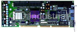
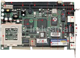
PORTWELL ROBO-8712VLA-Z102
Description
Intel Pentium 4 or Celeron processor based PICMG SBC with DDR SDRAM, AGP VGA, Fast Ethernet, Audeio and USB2.0
Part Number
ROBO-8712VLA-Z102
Price
Request Quote
Manufacturer
PORTWELL
Lead Time
Request Quote
Category
Single Board Computers
Specifications
Form Factor
PICMG
ATX Power Control Interface
One 4-pin header to support ATX power control with Modem Ring-On and
Audio
AC'97 2.2 Audio
Auxiliary I/O Interfaces
System reset switch, external speaker, Keyboard lock and HDD active LED, etc.
Chipset
Intel 845GV, Intel GMCH and Intel ICH4
CPU
Support one mPGA478 socket Pentium 4 Processor up to 3.06GHz, PSB speed 400/533 MHz, With standard CPU retention for easy heat sink and fan installation, 512KB or 256KB L2 Cache Memory Intel® Pentium® 4 or Celeron Processor
CPU Cooling Fan
Support one 3-pin header with wafer
Dimensions
338.5mm(L)x122mm(W) / 13.33"(L)x4.8"(W)
Ethernet
10Base-T/100Base-TX Ethernet; IEEE 802.3u auto-negotiation; One RJ-45 connector with two LE indicators
Expansion Interface
Proprietary PCI connection interface
Hardware Monitoring
Support CPU voltage, temperature and FAN monitoring
I/O
4 high driving GPIO (programmable GPI or GPO)
IrDa port
Three
ISA Bus
64mA high driving ISA Bus interface to backplane
Keyboard and Mouse
1 One 6-pin Mini Din connector for keyboard and mouse; One 5-pin header for external keyboard connection
LAN
One RJ45 connector
Main Memory
Two 184-pin DIMM sockets, Supports 200/266Mhz DDR SDRAM up to 2GB, Available bandwidth up to 2.1GB/s (DDR266), 64/128/256/512 MB SDRAM technologies, 2.5V DDR SDRAM support, Registered DIMM not supported, Do not support ECC functionality
Operating Temp.
0 to 55C
Parallel Port
One
PCB
8-layer
Power Requirement
+5V@2.8A; +12V(CPU)@4.0A; +12V(system)@0.8A
Processor
Intel Pentium 4 Celeron
Real Time Clock/Calender (RTC)
Support Y2K Real Time Clock/Calendar with battery backup for 7-year data retention, A high quality external Li battery.
Relative Humidity
5% to 90%, non-condensing
Serial Port
Two
SSD
Reserved one 32-pin socket for M-systems Flash Disk (Disk-on-Chip,DOC) up to 512MB. DOS, Windows, Win95, NT (bootable) drivers and Utility supported.
Storage Temp.
-20 to 80C
System BIOS
Phoenix - Award BIOS with PC’98 support
USB
1 USB port
Three USB 2.0 Ports
VGA
Intel GMCH integrated graphics controller; Dynamic 8 ~ 64MB shared display memory (Intel DVMT); Display resolution up to 2048xx1536 @ 60Hz refresh; Superior 2D, 3D and Video performance
Watchdog Timer
Support WDT function through software programming. Generate system reset or NMI.
Features
- 12V power connector
- Battery
- BIOS
- COM1/RS-232
- CON2/RS232/422/485
- DOC socket
- Factory optional DVO connectors
- FDC Interface connector
- Intel 845GV
- Intel ICH4
- Internal K/B connector
- K/B pin header
- LAN/RJ45
- mPGA478 Socket Pentium 4 processor up to 2.4GHz
- Parallel port
- PCI Extension connector
- Power connectors for stand alone operation
- PS/2 keyboard and mouse connector
- Two 184-pin DIMM sockets
- Two IDE connectors
- USB port
- VGA port
Datasheet

Extracted Text
ROBO-8712VLA
Single Board Computer
User's Manual
P/N: B8980850 Version 1.4
Copyright © Portwell, Inc., 2004. All rights reserved.
All other brand names are registered trademarks of their respective owners.
Preface
Table of Contents
How to Use This Manual
Chapter 1 System Overview.......................................................................................................1-1
1.1 Introduction.................................................................................................................................. 1-1
1.2 Check List ..................................................................................................................................... 1-2
1.3 Product Specification .................................................................................................................. 1-2
1.3.1 Mechanical Drawing......................................................................................................... 1-6
1.4 System Architecture .................................................................................................................... 1-6
Chapter 2 Hardware Configuration ...........................................................................................2-1
2.1 Jumper Setting ............................................................................................................................. 2-1
2.2 Connector Allocation .................................................................................................................. 2-2
Chapter 3 System Installation....................................................................................................3-1
3.1 Pentium 4 Processor.................................................................................................................... 3-1
3.2 Main Memory .............................................................................................................................. 3-2
3.3 M-systems Flash Disk ................................................................................................................. 3-2
3.4 Installing the Single Board Computer ...................................................................................... 3-3
3.4.1 Chipset Component Driver.............................................................................................. 3-3
3.4.2 Intel Integrated Graphics GMCH Chip.......................................................................... 3-3
3.4.3 On-board Fast Ethernet Controller ................................................................................. 3-4
3.4.4 On-board AC-97 Audio Device....................................................................................... 3-4
3.4.5 On-board 68-pin PCI connector....................................................................................... 3-4
3.5 Clear CMOS Operation............................................................................................................... 3-5
3.6 WDT Function.............................................................................................................................. 3-5
3.7 On-Board USB 2.0 Controller..................................................................................................... 3-6
3.8 Panel Display Output (Factory Optional only) ....................................................................... 3-7
3.9 GPIO.............................................................................................................................................. 3-7
Chapter 4 BIOS Setup Information............................................................................................4-1
4.1 Entering Setup.............................................................................................................................. 4-1
4.2 Main Menu ................................................................................................................................... 4-2
4.3 Standard CMOS Setup Menu ....................................................................................................4-3
4.4 IDE Adaptors Setup Menu......................................................................................................... 4-5
4.5 Advanced BIOS Feature ............................................................................................................. 4-6
4.6 Advanced Chipset Feature......................................................................................................... 4-9
4.7 Integrated Peripherals .............................................................................................................. 4-12
4.8 Power Management Setup ....................................................................................................... 4-17
4.9 PnP/PCI Configurations .......................................................................................................... 4-21
4.10 PC Health Status...................................................................................................................... 4-24
4.11 Frequency/Voltage Control................................................................................................... 4-25
4.12 Default Menu ........................................................................................................................... 4-25
4.13 Supervisor/User Password Setting ...................................................................................... 4-26
4.14 Exiting Selection ...................................................................................................................... 4-27
Chapter 5 Troubleshooting ........................................................................................................5-1
5.1 Backplane Setup........................................................................................................................... 5-1
5.2 Onboard Hardware Installation ................................................................................................ 5-4
5.3 BIOS Setting.................................................................................................................................. 5-6
5.4 OS Diagnostics ............................................................................................................................. 5-7
Preface
How to Use This Manual
The manual describes how to configure your ROBO-8712VLA system to meet
various operating requirements. It is divided into five chapters, with each chapter
addressing a basic concept and operation of Single Board Computer.
Chapter 1: System Overview. This chapter presents what you have in the inside of
box and give you an overview of the product specifications and basic system
architecture for this model of single board computer.
Chapter 2: Hardware Configuration Setting. This chapter shows the definitions and
locations of Jumpers and Connectors that you can easily configure your system.
Chapter 3: System Installation. This chapter describes how to properly mount the
CPU and main memory, M-system Flash disk, or optional flat panel display interface
module if any to get a safe installation and give you a programming guide of Watch
Dog Timer function. Besides, it will introduce and show you the driver installation
procedure about Graphics Controller.
Chapter 4: BIOS Setup Information. This chapter specifies the meaning of each
setup parameters and how to get advanced BIOS performance and update new
BIOS. In addition, POST checkpoint list will give you a guide of trouble-shooting.
Chapter 5: Troubleshooting. This chapter provides you a few useful tips to quickly
get your ROBO-8712VLA running with no failure. As basic hardware installation has
been addressed in Chapter 3, this chapter will basically focus on system integration
issues, in terms of backplane setup, BIOS setting, and OS diagnostics.
The content of this manual and EC declaration document is subject to change
without prior notice. These changes will be incorporated in new editions of the
document. Portwell may make supplement or change in the products described in
this document at any time.
Updates to this manual, technical clarification, and answers to frequently asked
questions will be shown on the following web site: http://www.portwell.com/.
Preface
EC Declaration of Conformity
(To Be Added)
For the following equipment:
Product Name:
Model Name:
Trade Name:
is herewith confirmed to comply with the requirements set out in the Council
Directive on the Approximation of the Laws of the Member States relating to
Electromagnetic Compatibility Directive (89/336/EEC). The equipment was
evaluated and passed the test, the following standards were applied :
EMC : EN 55022 (1994/A1:1995 Class A)
EN 50082-2 (1991)
EN 61000-4-2 (1995)
EN 61000-4-3 (1996)
EN 61000-4-4 (1995)
EN 61000-3-2 (1995)
EN 61000-3-3 (1995)
The following manufacturer is responsible for this declaration :
Portwell, Inc.
(Company Name)
3F, No.88, Sec. 1, Nei-Hu Rd., Taipei, Taiwan, R.O.C.
(Company Address)
Taipei, R.O.C.
Place Date Legal Signature of
Authorized Person
Preface
WARNING
� Remove Processor
Caution: Do not pull out processor without opening socket handle!
� High viscosity thermal grease between processor and cooler will lead the processor be
pulled out from socket when taking cooler off.
� This action may damage processor socket, which will cause poor contact between CPU
& socket.
� Handling SBC
Caution: Do not just hold any single side of the SBC; hold evenly on both sides!
� Heavy processor cooler shall bend the SBC when SBC being held just on one side.
� The bending may cause serious soldering or circuit damage.
System Overview
Chapter 1
System Overview
1.1 Introduction
ROBO-8712VLA is a cost effective and high integration Pentium 4 applied
computing platform. It provides innovative, high integration, high quality Single
Board Computers in the applied computing market. The board is based on Intel
845GV chipset and support Intel latest high performance processor, Intel Socket 478
Pentium® 4 Processor, running at up to 3.06Ghz with 533Mhz Process system bus
that built on Intel ® 0.13 micron processor technology.
With Intel 845GV chipset that support high speed non-ECC DDR SDRAM, high-
performance graphic controller AGP 4X controller and Intel fast Ethernet connection
enable ROBO-8712VLA to provide most versatile SBC in the market.
ROBO-8712VLA was designed to meet all kind of applied computing application.
With Intel most advance mainstream chipset 845GV ROBO-8712VLA is aiming the
most wide range of Multimedia and networking application in the market.
Its proprietary PCI extension connector provides an easy way to add additional
functions like U160 SCSI or 2nd LAN device in minutes.
It’s compact design with industry PICMG standard form factor make it the best
solution for high density server. High reliability and easy-to-maintain nature (lower
MTTR) meet high-availability need of Mission critical application.
ROBO-8712VLA User’s Manual 1-1
System Overview
1.2 Check List
The ROBO-8712VLA package should cover the following basic items:
� One ROBO-8712VLA single board computer
� One serial port kit with two COM ports
� One Parallel port cable kit
� One FDC cable
� One IDE cable
� One Y-cable cable for PS/2 keyboard and mouse
� One 4-pin ATX power control cable for backplane connection
� One Installation Resources CD-Title
� CPU holder
� One booklet of ROBO-8712VLA manual
� One Multimedia kit with MIC, Line In, Line Out and Single-port USB connectors
(Optional Accessory, not included in standard package)
If any of these items is damaged or missing, please contact your vendor and keep all
packing materials for future replacement and maintenance.
1.3 Product Specification
Main Features
� Intel 845GV based PICMG SBC with VGA/LAN/Audio and optional SCSI 160 or
nd
2 LAN module through proprietary connector (PCI bus)
� Support mPGA478 socket Pentium 4
� PSB speed 400/533 MHz
� Support DDR200/266 DDR SDRAM memory up to 2GB without ECC support
� Intel GMCH integrated graphic device with up to 64MB Dynamic display
memory
� ICH4 integrated fast Ethernet controller
� Support two a DMA/33/66/100 IDE
� Support Standard I/O including 2 serial ports, 1parallel port, one IrDA port, 3
USB ports (USB 2.0 compliant) and 8 high driving GPIO.
� Compliant with PCI Bus spec V2.1
� Full-size All-in-one SBC with PICMG 1.0 Rev 2.0 compliant
nd
� Proprietary socket for optional daughter board (PCI bus) for SCSI or 2 LAN
options
ROBO-8712VLA User’s Manual 1-2
System Overview
System Specifications
� Chipset
- Intel 845GV
- Intel GMCH and Intel ICH4
� CPU
- Support one mPGA478 socket Pentium 4 Processor up to 3.06GHz
- PSB speed 400/533 MHz
- With standard CPU retention for easy heat sink and fan installation
- 512KB or 256KB L2 Cache Memory Intel® Pentium® 4 or Celeron Processor
� Main memory
- Two 184-pin DIMM sockets
- Supports 200/266Mhz DDR SDRAM up to 2GB
- Available bandwidth up to 2.1GB/s (DDR266)
- 64/128/256/512 MB SDRAM technologies
- 2.5V DDR SDRAM support
- Registered DIMM not supported
- Do not support ECC functionality
� System BIOS
- Phoenix - Award BIOS with PC’98 support
- 4Mbit flash ROM (Intel FWH) for easy upgrade
- Support DMI, PnP, Green function and ACPI
- ACPI support suspend to RAM, USB wake up.
� On Board I/O
- PCI IDE Interface
Support two enhanced IDE channel up to four HDDs with PIO mode 4, Ultra
DMA/33/66/100 model transfer and Bus master feature.
- Floppy Drive Interface
Support one FDD port up to two floppy drives and 5-1/4"(360K, 1.2MB), 3-1/2"
(720K, 1.2MB, 1.44MB, 2.88MB) diskette format and 3-mode FDD
- Serial Ports
Support two high-speed 16C550 compatible UARTs with 16-byte T/R FIFOs
RS-232/422/485 selectable for COM2 by jumper
- IR Interface
Support one 6-pin header for serial Standard Infrared wireless communication
Shared with one serial port
- Parallel Port
Support one parallel port with SPP, EPP and ECP modes
- USB Interface
USB 2.0 compliant
Support three USB (Universal Serial Bus) ports for high-speed I/O peripheral
devices
One on bracket; two with pin header
ROBO-8712VLA User’s Manual 1-3
System Overview
- PS/2 Mouse and Keyboard Interface
Support one 6-pin Mini-DIN connector for PS/2 mouse/keyboard connection
through Y-Cable separation and one 5-pin shrouded connector for PS/2
keyboard connection through backplane connection
� Auxiliary I/O
- One 2-pin system reset switch
- One 4-pin external speaker interface
- One 5-pin key-lock header
- One 2-pin HDD active indicator interface
- One 8-pin USB dual port interface
- One 4-pin ATX power control interface
- One 10-pin connector for GPIO (4 GPI and 4 GPO)
� Bracket
- Support one RJ45 connectors (LAN)
- One VGA connector
- One USB Port
- One PS/2 Keyboard/mouse connector (Mini din)
� Hardware Monitoring
Support CPU voltage, temperature and FAN monitoring
� Watchdog Timer
- Support WDT function through software programming
- Software programmable time-out internal setting
- Generate system reset or NMI
� Solid State Disk (SSD)
- Reserved one 32-pin socket for M-systems Flash Disk (Disk-on-Chip,DOC) up
to 512MB
- DOS, Windows, Win95, NT (bootable) drivers and Utility supported
� Real Time Clock/Calendar (RTC)
- Support Y2K Real Time Clock/Calendar with battery backup for 7-year data
retention
- A high quality external Li battery
� ACPI compliant support the full-on (S0), Stop Grant (S1), Suspend to RAM (S3),
Suspend to Disk (S4), and soft-off (S5) power management states.
� ATX Power Control Interface
One 4-pin header to support ATX power control with Modem Ring-On and
Wake-On-LAN function
� Auxiliary I/O Interfaces
System reset switch, external speaker, Keyboard lock and HDD active LED, etc.
� Power Good
On-Board power good generator with 200 ms to 300 ms reset duration
� CPU Cooling Fan
Support one 3-pin header with wafer
ROBO-8712VLA User’s Manual 1-4
System Overview
Additional Main Peripheral Function
� On Board High performance Graphics (Intel GMCH Integrated Graphics
controller)
- IGD with analog display port
- Analog Display Support up to 2048 x 1536 @ 60Hz refresh
- AGP 2.0, AGP 4X. 1.5V
- Software DVD at 30 fps, full screen
- Motion Video Acceleration
� One On Board Ethernet (one ICH4 Integrated MAC controller with external
10/100 Mb phy)
- Support 10/100 MB Base-TX
- One RJ-45 phone jack.
- Support two LEDs to indicator LAN access and link status on RJ45 jack
- Support Wake-on-LAN
� PICMG Compliant PCI plus ISA bus Interface
- Follow PICMG 1.0 Rev 2.0 standard (32-bit PCI and 16-bit ISA)
- Fully complies with PCI Local Bus specification V2.1 (support 4 master PCI
slots)
� On Board PCI to ISA Bridge
- Support ISA Bus mastering
- Support standard ISA slot
- 64mA high driving
- Support M-system DOC
� ISA64 High ISA-Bus Driving Capability
Support 64mA high driving capability for ISA-Bus slots on back plane
� On-board 68-pin PCI connector
Support one additional PCI daughter board
� Optional daughter Board Ultra 160 SCSI (AIC 7892 chipset)
- Support Portwell Proprietary PCI connector
- Support one 68-pin SCSI interface
- SCSI data transfers up to 160MB/sec
� Physical and Environmental requirements
- Outline Dimension (L x W) 338.5mm (13.33”) X 122mm (4.8”)
- Power Requirements:
. +12V (CPU) @4.0A
. +12V (System) @0.8A
. +5V @2.8A
- Test configuration:
. CPU: Intel P4 2.4GHz/533MHz FSB/512KB L2 Cache
. Memory: DDR SDRAM 512MBx2
. Primary Master IDE HDD: Samsung SV2042H (20GB)
. OS: Microsoft Windows 2000 + SP2
ROBO-8712VLA User’s Manual 1-5
System Overview
. Test Programs: 3D Mark 2001 for loading VGA and Burning Test V2.2 for
loading CPU
. Connected Fans: Only CPU fan connected
. Run Time: 10 minutes
- Operating Temperature: 0°C ~ 55°C (32°F ~ 131°F)
- Storage Temperature: -20°C ~ 80°C
- Relative Humidity: 0% ~ 95%, non-condensing
1.3.1 Mechanical Drawing
87.12
4- Holes ?4.0
5
5
4- Pad ?10.4
5 86.35 25.39
43.43 76.20 1.50
338.58
1.4 System Architecture
The system architecture of ROBO-8712VLA includes two main Intel chips, Intel
845GV chipset supports Pentium-4/Celeron processor, DDR-SDRAM, 2D/3D
graphic display, and its ICH4 supports PCI bus interface, APM, ACPI compliant
power management, USB port, SMBus communication, and Ultra DMA/33/66/100
IDE Master, and it also provides a Fast Ethernet controller. The W83627HF (I/O
Controller) is responsible for PS/2 Keyboard/Mouse, UARTs, FDC, Hardware
Monitor, Parallel, Watch Dog Timer and Infrared interface.
The special pin configuration of the CPU socket adopts the 478 pins in total. This
new generation CPU provides better performance to many applications.
The PCI-to-ISA bridge supports a standard 16-bit ISA bus interface which is applied
for all slower I/O operations. In ROBO-8712VLA, it supports DiskOnChip (DOC) for
M-systems Flash disk.
ROBO-8712VLA User’s Manual 1-6
121.89
22.33 59.43
5.21
5
5.66
5
7.62
99.82
System Overview
There is one on-board PCI Fast Ethernet via RJ-45 Ports to support full functionality
of ROBO-8712VLA AIO SBC (All-In-One Single Board Computer).
The on-board 68-pin PCI connector supports one additional PCI daughter board for
further extension.
R R
Intel Pentium 4
CLOCK GENERATOR
Processor/
Northwood Processor
HOST BUS (400/533 MHz)
1
2 DDR MEMORY x 2 (up
2
to 2GB in total)
DDR 200/266
CRT
82845GV
DVO
GMCH
(Optional)
Hub Link
2 ATA 100 IDE Channels
82801DA
IDE Bus Master
ICH4
PCI BUS
IDE 1 IDE 2
(420 EBGA)
MAC
3 x USB 2.0 PORTS
Intel 82562
LPC
ITE IT8888
LAN
DiskOnChip BUFFER
2UART/LPT/FDD/IR
SUPER I/O
W83627HF
Keyboard
ISA BUS
Hardware
WDT
Monitor Golden Finger
Mouse
ROBO-8712VLA System Block Diagram
ROBO-8712VLA User’s Manual 1-7
Hardware Configuration
Chapter 2
Hardware Configuration
This chapter indicates jumpers’, headers’ and connectors’ locations. Users may find
useful information related to hardware settings in this chapter. The default settings
are indicated with a star sign (Ì).
2.1 Jumper Setting
For users to customize ROBO-8712VLA’s features. In the following sections, Short
means covering a jumper cap over jumper pins; Open or N/C (Not Connected)
means removing a jumper cap from jumper pins.
Users can refer to Figure 2-1 for the Jumper locations.
J26 J1 J11
DIMM1 J2 J3
JP1
DIMM2
J29
J8 J9 J25
J38
J5
J31
J24
JP2
J4 JP3 J37 J10
ICH4 J32 J33 J28 J30 J27 J12
J15
845
BAT
J18 J13
J23
J19
J36
J14
J16
J35
J34
BZ
U26
J20
J7
J6
Figure 2-1 ROBO-8712VLA Jumper/Connector Location
JP1: CMOS Clear
JP1 Function
1-2 Short Normal Operation Ì
2-3 Short Clear CMOS / Contents
JP2: COM2(J9) Interface Selection
JP2
5-6,9-11,10-12,15-17,16-18 Short RS-232 Ì
3-4,7-9,8-10,13-15,14-16,21-22 Short RS-422
1-2,7-9,8-10,19-20 Short RS-485
ROBO-8712VLA User’s Manual 2-1
MPGA478B
Hardware Configuration
JP3: AT/ATX Power Selection
JP3
1-3, 2-4 Short AT Power
3-5,4-6 Short ATX Power Ì
2.2 Connector Allocation
I/O peripheral devices and flash disk are connected to the interface connectors and
DOC socket on this single board computer (Figure 2-1)
Connector’s Function List
Connector Function Remark
J1 Primary IDE Connector (IDE1)
J2 Secondary IDE Connector (IDE2)
J3 FDC Interface Connector
J5 Power FAN Connector
J6 CPU Fan Connector
J7 System Fan Connector
J8 COM1 Serial Port (RS-232)
J9 COM2 Serial Port (RS-232/422/485)
J10 External Wake On LAN Connector
J11 Parallel Port Connector
J12 IrDA Connector
J13 PS/2 keyboard/Mouse Connector 6-pin Mini-DIN
J14 External keyboard Connector Connect to Backplane
J15 Single-port USB Connector
J16 External USB Connector
J18 Audio MIC/Line-in/Line-out
J19 Audio CD-in Connector
J20 On-board VGA CRT Connector
J23 68-pin PCI Connector
J24 Ethernet RJ-45 Connector
J25 General Purpose I/O Connector
J26 12V CPU Power Connector Must to connect
J27 Hard Disk Drive LED Connector Connect to Chassis
J28 External Speaker Connector Connect to Chassis
J29 ATX Power Control Connector Connect to Backplane
J30 Power LED and Keyboard Lock Connect to Chassis
J31 Standalone Power Connector Only for standard one
J32 ATX Power Button Interface Connect to Chassis
J33 Reset Button Connector Connect to Chassis
J34 DVO Power Connector Optional
J35 DVO Connector -1 Optional
J36 DVO Connector -2 Optional
J38 Front SMBus Connector
ROBO-8712VLA User’s Manual 2-2
Hardware Configuration
Pin Assignments of Connectors
J1/J2: Primary/Secondary IDE Connector (IDE1/IDE2)
PIN No. Signal Description PIN No. Signal Description
1 RESET# 2 Ground
3 Data 7 4 Data 8
5 Data 6 6 Data 9
7 Data 5 8 Data 10
9 Data 4 10 Data 11
11 Data 3 12 Data 12
13 Data 2 14 Data 13
15 Data 1 16 Data 14
17 Data 0 18 Data 15
19 Ground 20 N/C
21 DMA REQ 22 Ground
23 IOW# 24 Ground
25 IOR# 26 Ground
27 IOCHRDY 28 Pull-down
29 DMA ACK# 30 Ground
31 INT REQ 32 N/C
33 DA1 34 CBLID#
35 DA0 36 DA2
37 HDC CS0# 38 HDC CS1#
39 HDD Active# 40 Ground
J3: FDC Interface Connector
PIN No. Signal Description PIN No. Signal Description
1 Ground 2 Density Select 0
3 Ground 4 N/C
5 Ground 6 Density Select 1
7 Ground 8 Index#
9 Ground 10 Motor ENA#
11 Ground 12 Drive Select B#
13 Ground 14 Drive Select A#
15 Ground 16 Motor ENB#
17 Ground 18 Direction#
19 Ground 20 Step#
21 Ground 22 Write Data#
23 Ground 24 Write Gate#
25 Ground 26 Track 0#
27 Ground 28 Write Protect#
ROBO-8712VLA User’s Manual 2-3
Hardware Configuration
29 N/C 30 Read Data#
31 Ground 32 Head Select#
33 N/C 34 Disk Change#
J5/J6/J7 : Power/CPU/System Fan Connector
PIN No. Signal Description
1 Ground
2 +12V
3 Fan Speed Detecting signal
Note:
The fan must be a 12V fan. And there is not any over current protection.
J8/J9: COM1/COM2 Serial Port 1/2 Connector
PIN No. Signal Description
RS-232 RS-422 RS-485
1 DCD (Data Carrier Detect) TX- DATA-
2 RXD (Receive Data) TX+ DATA+
3 TXD (Transmit Data) RX+ N/C
4 DTR (Data Terminal RX- N/C
Ready)
5 GND (Ground) GND GND
6 DSR (Data Set Ready) N/C N/C
7 RTS (Request to Send) N/C N/C
8 CTS (Clear to Send) N/C N/C
9 RI (Ring Indicator) N/C N/C
10 N/C N/C N/C
Notes:
1) J8 is fixed as RS-232
2) J9 is configurable as RS-232/422/485 with jumper JP2
J10: External Wake On LAN Connector
PIN No. Signal Description
1 5VSB
2 Ground
3 External WOL Signal Input (Active low)
ROBO-8712VLA User’s Manual 2-4
Hardware Configuration
J11: Parallel Port Connector
PIN No. Signal Description PIN No. Signal Description
1 Strobe# 14 Auto Form Feed#
2 Data 0 15 Error#
3 Data 1 16 Initialization#
4 Data 2 17 Printer Select IN#
5 Data 3 18 Ground
6 Data 4 19 Ground
7 Data 5 20 Ground
8 Data 6 21 Ground
9 Data 7 22 Ground
10 Acknowledge# 23 Ground
11 Busy 24 Ground
12 Paper Empty 25 Ground
13 Printer Select 26 N/C
J12: IrDA Connector
PIN No. Signal Description
1 +5V
2 N/C
3 IRRX
4 Ground
5 IRTX
6 N/C
J13: PS/2 Keyboard/Mouse Connector
PIN No. Signal Description
1 Mouse Data
2 Keyboard Data
3 Ground
4 5V Dual
5 Mouse Clock
6 Keyboard Clock
ROBO-8712VLA User’s Manual 2-5
Hardware Configuration
J14: External Keyboard Connector
PIN No. Signal Description
1 Keyboard Clock
2 Keyboard Data
3 N/C
4 Ground
5 5V Dual
J15: Single-port USB Connector
PIN No. Signal Description
1 5V Dual
2 USB0-
3 USB0+
4 Ground
J16: External USB Connector
PIN No. Signal Description PIN No. Signal Description
1 5V Dual 2 Frame Ground
3 USB2- 4 Ground
5 USB2+ 6 USB3+
7 Ground 8 USB3-
9 Frame Ground 10 5V Dual
Note:
5V Dual is always available. It’s supplied by either 5V VCC power source in normal
operation mode or 5V standby power source in standby mode.
J18: Audio MIC/Line-in/Line-out Connector
PIN No. Signal Description PIN No. Signal Description
1 MIC with Reference Voltage 2 Analog Ground
3 Line-in Left Channel 4 Analog Ground
5 Line-in Right Channel 6 Analog Ground
7 Line-out Left Channel 8 Analog Ground
9 Line-out Right Channel 10 N/C
Note:
The Reference Voltage on MIC signal offers 2.25V~2.75V with 5mA drive
ROBO-8712VLA User’s Manual 2-6
Hardware Configuration
J19: Audio CD-in Connector
PIN No Signal Description
1 CD-in Left Channel
2 CD Ground
3 CD Ground
4 CD-in Right Channel
J20: On-board VGA CRT Connector
PIN No. Signal Description
1 Red
2 Green
3 Blue
4 Monitor ID0 (MONID0) (5V I/F)
5 Ground
6 Ground
7 Ground
8 Ground
9 N/C
10 Ground
11 Monitor ID1 (MONID1) (5V I/F)
12 VGA DDC Data (5V I/F)
13 Horizontal Sync. (HSYNC) (5V I/F)
14 Vertical Sync. (VSYNC) (5V I/F)
15 VGA DDC Clock (5V I/F)
ROBO-8712VLA User’s Manual 2-7
Hardware Configuration
J23: 68-pin PCI Connector
PIN No. Signal Description PIN No. Signal Description
1 +5V 2 AD0
3 AD1 4 AD2
5 AD3 6 AD4
7 AD5 8 AD6
9 AD7 10 Ground
11 +5V 12 AD8
13 AD9 14 AD10
15 AD11 16 AD12
17 AD13 18 AD14
19 AD15 20 Ground
21 +5V 22 AD16
23 AD17 24 AD18
25 AD19 26 AD20
27 AD21 28 AD22
29 AD23 30 Ground
31 +5V 32 AD24
33 AD25 34 AD26
35 AD27 36 AD28
37 AD29 38 AD30
39 AD31 40 Ground
41 +5V 42 C/BE#0
43 C/BE#1 44 C/BE#2
45 C/BE#3 46 PAR
47 FRAME# 48 TRDY#
49 IRDY# 50 Ground
51 +5V 52 STOP#
53 DEVSEL# 54 PERR#
55 SERR# 56 REQ#4
57 GNT#4 58 REQ#5
59 GNT#5 60 Ground
61 PCI Clock1 62 PCI Clock2
63 PCIRST# 64 LOCK#
65 IRQ#A 66 IRQ#B
67 IRQ#C 68 IRQ#D
ROBO-8712VLA User’s Manual 2-8
Hardware Configuration
J24: Ethernet RJ-45 Connector
PIN No. Signal Description
1 TD+
2 TD-
3 TDC
4 Termination to Ground
5 Termination to Ground
6 RDC
7 RD+
8 RD-
J25: General Purpose I/O Connector
PIN No. Signal Description
1 General Purpose I/O Port 1 (GPIO1)
2 General Purpose I/O Port 2 (GPIO2)
3 General Purpose I/O Port 3 (GPIO3)
4 General Purpose I/O Port 4 (GPIO4)
5 Ground
6 Buffered Digital Output Port 1 (DO1)
7 Buffered Digital Output Port 2 (DO2)
8 Buffered Digital Output Port 3 (DO3)
9 Buffered Digital Output Port 4 (DO4)
10 +5V
Notes:
1) All General Purpose I/O ports can only adapt standard TTL ± 5% signal level
(0V/5V). Pin 1~4 can be either input or output, while pin 6-10 can only be digital
output.
2) The 4 extra DO ports are provided for the applications that need higher driving
capability. Through invert amplitude respected to GPIO port, each open-drain DO
port can stand maximum fan out for up to 100mA, rather than 12mA direct driven
by GPIO port.
J26: 12V CPU Supplementary Connector
PIN No. Signal Description
1 Ground
2 Ground
3 +12V
4 +12V
ROBO-8712VLA User’s Manual 2-9
Hardware Configuration
J27: Hard Disk Drive LED Connector
PIN No. Signal Description
1 +5V (390 ohm pull-up for HDD LED+)
2 HDD Active # (HDD LED-)
J28: External Speaker Connector
PIN No. Signal Description
1 Speaker Signal Output (Open-drain w/
internal series 33 Ohm)
2 N/C
3 Ground
4 +5V
Note:
The pull-high voltage of external speaker is limited at 5V maximum.
J29: ATX Power Control Connector
PIN No. Signal Description
1 ATX Power Good Signal (PW-OK)
2 ATX 5V Stand-by (5VSB)
3 ATX Power On Control (PS-ON)
4 Ground
J30: Power LED and Keyboard Lock Connector
PIN No. Signal Description
1 +5V (470 Ohm pull-up for power LED+)
2 N/C
3 Ground (For Power LED-)
4 Keyboard Lock Signal Input (Active low)
5 Ground
ROBO-8712VLA User’s Manual 2-10
Hardware Configuration
J31: Standalone Power Connector
PIN No. Signal Description
1 +12V
2 Ground
3 Ground
4 +5V
Notes:
1) To run system in standalone operation. Both J26 and J31 have to be connected.
2) Some of USB 2.0 devices need large current consumption. It is helpful for them
to detect by system while Standalone Power connector is connected on SBC.
J32: ATX Power button Interface
PIN No. Signal Description
1 Pull-high 1K Ohm to +5V
2 Power Button Signal Input (Active high)
J33: Reset Button Connector
PIN No Signal Description
1 Reset Signal Input (Active low)
2 Ground
J34: DVO Power Connector
PIN No. Signal Description
1 +12V
2 +5V
3 +3.3V
4 Ground
5 Ground
ROBO-8712VLA User’s Manual 2-11
Hardware Configuration
J35: DVO Connector-1 (Factory Optional for Panel Display Kit only); not
populated with standard module
PIN No. Signal Description PIN No. Signal Description
1 DVOCD0 2 DVOCD1
3 DVOCD2 4 DVOCD3
5 DVOCD4 6 DVOCD5
7 DVOCD6 8 DVOCD7
9 DVOCD8 10 DVOCD9
11 DVOCD10 12 DVOCD11
13 DVOCCLK 14 DVOCCLK#
15 DVOCVSYNC 16 DVOCHSYNC
17 DVOCFLDSTL 18 DVOCBLANK#
19 DVOBCCLKINT 20 DVOBCINTR#
21 Ground 22 +3.3V
23 MDDC_CLK 24 MDDC_DATA
25 MI2CCLK 26 MI2CDATA
27 MDVI_CLK 28 MDVI_DATA
29 Ground 30 +5V
31 ADDIN0 32 ADDIN1
33 ADDIN2 34 ADDIN3
35 ADDIN4 36 ADDIN5
37 ADDIN6 38 ADDIN7
39 CHIPRST- 40 +1.5V
J36: DVO Connector-2 (Factory Optional for Panel Display Kit only); not
populated on the standard module
PIN No. Signal Description PIN No. Signal Description
1 DVOBD0 2 DVOBD1
3 DVOBD2 4 DVOBD3
5 DVOBD4 6 DVOBD5
7 DVOBD6 8 DVOBD7
9 DVOBD8 10 DVOBD9
11 DVOBD10 12 DVOBD11
13 DVOBCLK 14 DVOBCLK#
15 DVOBVSYNC 16 DVOBHSYNC
17 DVOBFLDSTL 18 DVOBCCLKINT
19 Ground 20 +3.3V
ROBO-8712VLA User’s Manual 2-12
Hardware Configuration
J38: Front SMBus Connector
PIN No. Signal Description
1 SMBCLK
2 N/C
3 Ground
4 SMBDATA
5 +5V
ROBO-8712VLA User’s Manual 2-13
System Installation
Chapter 3
System Installation
This chapter provides you with instructions to set up your system. The additional
information is enclosed to help you install M-systems Flash disk, set up onboard PCI
device and handle WDT operation in software programming.
3.1 Pentium 4 Processor
Installing 478 Pin CPU
1) Lift the handling lever of CPU socket outwards and upwards to the other end.
2) Align the processor pins with pinholes on the socket. Make sure that the notched
corner or dot mark (pin 1) of the CPU corresponds to the socket’s bevel end. Then
press the CPU gently until it fits into place. If this operation is not easy or smooth,
don’t do it forcibly. You need to check and rebuild the CPU pin uniformly.
3) Push down the lever to lock processor chip into the socket once CPU fits.
4) Follow the installation guide of cooling fan or heat sink to mount it on CPU
surface and lock it on the socket 478.
Note:
You should know Pentium 4 processor need extra 12V power source. DON’T
FORGET TO CONNECT 4pin 12V connector to J26!
Removing CPU
1) Unlock the cooling fan first.
2) Lift the lever of CPU socket outwards and upwards to the other end.
3) Carefully lift up the existing CPU to remove it from the socket.
4) Follow the steps of installing a CPU to change to another one or place handling
bar to close the opened socket.
Configuring System Bus
ROBO-8712VLA will automatically detect the CPU used. CPU speed of Intel P4 can
be detected automatically.
ROBO-8712VLA User’s Manual 3-1
System Installation
3.2 Main Memory
ROBO-8712VLA provides two DDR-SDRAM DIMM slots to support 2.5V DDR-
SDRAM as on-board main memory. The maximum memory size can be up to 2GB.
Auto detecting memory clock according to BIOS CMOS settings.
For system compatibility and stability, don’t use memory module without brand.
You can also use only one double-sided DIMM in either one DIMM slot or two
single-sided DIMM in both slots.
Watch out the contact and lock integrity of memory module with socket, it will
impact on the system reliability. Follow normal procedures to install your DRAM
module into memory socket. Before locking, make sure that all modules have been
fully inserted into the card slots.
Note:
To maintain system stability, don’t change any of DRAM parameters in BIOS setup
to upgrade your system performance without acquiring technical information.
3.3 M-systems Flash Disk
ROBO-8712VLA reserves one 32-pin DIP sockets for installing M-systems Flash disk
from 2MB to 288MB. This operation structure is running with pure ISA-bus without
PnP (Plug and Play) function. Before installing, make sure that I/O address jumper
setting is set on right position to prevent unworkable system due to I/O resource
conflict. Do remember to follow DOC (DiskOnChip) installation procedure.
Otherwise, it is possible to burn out the Flash chip due to incorrect installation.
Installing DOC
Align the DOC with pinholes on the socket. Make sure that the notched corner or dot
mark (pin 1) of DOC corresponds to notched corner of the socket. Then press the
DOC gently until it fits into place. If installation procedure is correct, the Flash disk
can be viewed as a normal hard disk to access read/write data.
WARNING
Please ensure that your DOC is properly inserted. Placing the DOC in reverse will
cause severe damage. Remember, a new DOC chip is always a formatted disk. You
may simply plug the chip on the DOC socket and read/write through it. If you
would like to boot from this Flash disk, it is necessary to refer to the application note
from M-systems. You can easily get relative information from M-systems shipping
package (such as product manual) or Web-site http://www.m-sys.com.
ROBO-8712VLA User’s Manual 3-2
System Installation
3.4 Installing the Single Board Computer
To install your ROBO-8712VLA into standard chassis or proprietary environment,
you need to perform the following:
Step 1 : Check all jumpers setting on proper position
Step 2 : Install and configure CPU and memory module on right position
Step 3 : Place ROBO-8712VLA into the dedicated position in your system
Step 4 : Attach cables to existing peripheral devices and secure it
WARNING
Please ensure that your SBC is properly inserted and fixed by mechanism.
Otherwise, the system might be unstable or do not work due to bad contact of
PICMG 1.0 PCI plus ISA-bus slot.
Note:
Please refer to section 3-4-1 to 3-4-3 to install INF/VGA/LAN drivers.
3.4.1 Chipset Component Driver
The chipset on ROBO-8712VLA is a new chipset that a few old operating systems
might not be able to recognize. To overcome this compatibility issue, for Windows
Operating Systems such as Windows-95/98/98SE/2000, please install its INF before
any of other Drivers are installed. You can find very easily this chipset component
driver in ROBO-8712VLA CD-title.
3.4.2 Intel Integrated Graphics GMCH Chip
Using GMCH High performance graphic integrated chipset is aimed to gain an
outstanding graphic performance. It is accompanied by shared 8 to 64MB system
DDR-SDRAM with Intel DVMT. This combination makes ROBO-8712VLA an
excellent piece of multimedia hardware.
With no additional video adaptor, this onboard video will usually be the system
display output. By adjusting the BIOS setting to disable on-board VGA, an add-on
PCI or ISA VGA card can take over the system display.
Drivers Support
Please find 845G/GV GMCH driver in the ROBO-8712VLA CD-title. Drivers support
Windows-98/98SE/ME, Windows-NT 3.51/4.0, Windows-2000, OS2, and Linux.
(1) Windows-98/98SE: Please execute exe file to start graphics driver installation, or
bring up the Display Control Panel and update graphics driver.
ROBO-8712VLA User’s Manual 3-3
System Installation
(2) Windows-NT 4.0: Please install Windows-NT 4.0 Service Pack 4 or above first,
then execute exe file, or simply bring up the Display Control Panel and update
graphics driver.
(3) Windows-2000: Please bring up the Device Manager and update graphics drivers.
(4) Redhat Linux V6.2: Please refer to the related documentation in for graphic
drivers installation.
3.4.3 On-board Fast Ethernet Controller
Drivers Support
Please find Intel ICH4 LAN driver in /Ethernet directory of ROBO-8712VLA CD-
title. The drivers support Windows-NT 4.0, Windows-98/98SE/ME, Windows-2000,
Windows-XP, and Linux.
LED Indicator (for LAN status)
ROBO-8712VLA provides three LED indicators to report 82801BA MAC Fast
Ethernet interfaces status. Please refer to the table below as a quick reference guide.
Operation of Ethernet Port
82801BA Name of LED
ON Off
Amber LAN Linked & Linked Active (Blinking)
Active LED
Green LAN speed LED 100 Mbps 10 Mbps
3.4.4 On-board AC-97 Audio Device
The on-board AC-97 audio device provides a more than standard sound display. It is
capable for many general purposes.
3.4.5 On-board 68-pin PCI connector
ROBO-8712VLA provides one on-board 68-pin PCI connector that allows you to
apply additional PCI devices, such as SCSI or Ethernet. If you have a compatible PCI
device, simply plug it onto the connector and secure it with two retention bars.
ROBO-8712VLA User’s Manual 3-4
System Installation
3.5 Clear CMOS Operation
The following table indicates how to enable/disable CMOS Clear Function hardware
circuit by putting jumpers at proper position.
JP1 Function
1-2 Short Normal Operation ★
2-3 Short Clear CMOS contents
To correctly operate CMOS Clear function, users must turn off the system, move JP1
jumper to short pin 2 and 3. To clear CMOS contents, please turn the power back on
and turn it off again for AT system, or press the toggle switch a few times for ATX
system. Move the JP1 back to 1-2 position (Normal Operation) and start the system.
System will then produce a “CMOS Check Sum Error” message and hold up. Users
may then follow the displayed message to load BIOS default setting.
3.6 WDT Function
The working algorithm of the WDT function can be simply described as a counting
process. The Time-Out Interval can be set through software programming. The
availability of the time-out interval settings by software or hardware varies from
boards to boards.
ROBO-8712VLA allows users control WDT through dynamic software
programming. The WDT starts counting when it is activated. It sends out a signal to
system reset or to non-maskable interrupt (NMI), when time-out interval ends. To
prevent the time-out interval from running out, a re-trigger signal will need to be
sent before the counting reaches its end. This action will restart the counting process.
A well-written WDT program should keep the counting process running under
normal condition. WDT should never generate a system reset or NMI signal unless
the system runs into troubles.
The related Control Registers of WDT are all included in the following sample
program that is written in C language. User can fill a non-zero value into the Time-
out Value Register to enable/refresh WDT. System will be reset after the Time-out
Value to be counted down to zero. Or user can directly fill a zero value into Time-out
Value Register to disable WDT immediately. To ensure a successful accessing to the
content of desired Control Register, the sequence of following program codes should
be step-by-step run again when each register is accessed.
Additionally, there are maximum 2 seconds of counting tolerance that should be
considered into user’ application program. For more information about WDT, please
refer to Winbond W83627HF data sheet.
ROBO-8712VLA User’s Manual 3-5
System Installation
There are two PNP I/O port addresses that can be used to configure WDT,
1) 0x2E:EFIR (Extended Function Index Register, for identifying CR index number)
2) 0x2F:EFDR (Extended Function Data Register, for accessing desired CR)
Below are some example codes, which demonstrate the use of WDT.
// Enter Extended Function Mode
outp(0x002E, 0x87);
outp(0x002E, 0x87);
// Assign Pin 89 to be a WDTO
outp(0x002E, 0x2B);
outp(0x002F, inp(0x002F) & 0xEF);
// Select Logic Device 8
outp(0x002E, 0x07);
outp(0x002F, 0x08);
// Active Logic Device 8
outp(0x002E, 0x30);
outp(0x002F, 0x01);
// Select Count Mode
outp(0x002E, 0xF5);
outp(0x002F, (inp(0x002F) & 0xF7) | ( Count-mode Register & 0x08));
// Specify Time-out Value
outp(0x002E, 0xF6);
outp(0x002F, Time-out Value Register );
// Disable WDT reset by keyboard/mouse interrupts
outp(0x002E, 0xF7);
outp(0x002F, 0x00);
// Exit Extended Function Mode
outp(0x002E, 0xAA);
Definitions of Variables:
Value of Count-mode Register :
1) 0x00 -- Count down in seconds (Bit3=0)
2) 0x08 -- Count down in minutes (Bit3=1)
Value of Time-out Value Register :
1) 0x00 -- Time-out Disable
2) 0x01~0xFF -- Value for counting down
3.7 On-Board USB 2.0 Controller
Drivers Support
Please find Intel ICH4 USB driver in /USB20 directory of ROBO-8712VLA CD-title.
The drivers support Windows-2000 and Windows-XP.
ROBO-8712VLA User’s Manual 3-6
System Installation
3.8 Panel Display Output (Factory Optional only)
This is a factory optional function through a Portwell proprietary VDO connector
and a 5-pin shouted header for power control/source of backlight system.
There are two LCD panel interfaces can provided in this system, TMDS and LVDS
are two interfaces available on different panel kit.
A connection to one of these 2 different interfaces will result different signal line
impedance combinations. The selection will be made base on the different
impedances combinations.
3.9 GPIO
The ROBO-8712VLA provides 4 input/output ports that can be individually
configured to perform a simple basic I/O function. Users can configure each
individual port to become an input or output port by programming register bit of
I/O Selection. To invert port value, the setting of Inversion Register has to be made.
Port values can be set to read or write through Data Register.
Additionally, 4-extra Digital Output ports inversely amplified signals from GPIO
ports. There are open-drain buffers, which can offer greater driving capacity up to
100mA.
There are two PNP I/O port addresses that can be used to configure GPIO ports,
1) 0x2E - EFER (Extended Function Enable Register, for entering Extended Function
Mode)
- EFIR (Extended Function Index Register, for identifying CR index number)
2) 0x2F - EFDR (Extended Function Data Register, for accessing desired CR)
Below are some example codes, which demonstrate the use of GPIOs.
// Enter Extended Function Mode
outp(0x002E, 0x87);
outp(0x002E, 0x87);
// Assign Pin121-128 to be GPIO port 1
outp(0x002E, 0x2A);
outp(0x002F, inp(0x002F) | 0x84);
// Select Logic Device 7
outp(0x002E, 0x07);
outp(0x002F, 0x07);
// Active Logic Device 7
outp(0x002E, 0x30);
ROBO-8712VLA User’s Manual 3-7
System Installation
outp(0x002F, 0x01);
// Select Inversion Mode
outp(0x002E, 0xF2);
outp(0x002F, (inp(0x002F) & 0x0F) | ( Inversion Register & 0xF0));
// Select I/O Mode
outp(0x002E, 0xF0);
outp(0x002F, (inp(0x002F) & 0x0F) | ( I/O Selection Register & 0xF0));
// Access GPIO ports
outp(0x002E, 0xF1);
outp(0x002F, (inp(0x002F) & 0x0F) | ( Output Data & 0xF0));
or
Input Data = inp(0x002F);
// Exit Extended Function Mode
outp(0x002E, 0xAA);
Definitions of Variables:
Each bit in the high nibble of each Register represents the setting of a GPIO port.
Bit4 vs. GPIO port 1
Bit5 vs. GPIO port 2
Bit6 vs. GPIO port 3
Bit7 vs. GPIO port 4
Value of Inversion Register :
Only high nibble is available for this function.
When set to a ‘1’, the incoming/outgoing port value is inverted.
When set to a ‘0’, the incoming/outgoing port value is the same as in Data
Register.
Value of I/O Selection Register :
Only high nibble is available for this function.
When set to a ‘1’, respective GPIO port is programmed as an input port.
When set to a ‘0’, respective GPIO port is programmed as an output port.
Value of Output Data / Input Data :
Only high nibble is available for this function.
If a port is assigned to be an output port, then its respective bit can be
read/written.
If a port is assigned to be an input port, then its respective bit can be read
only.
Notes:
1) All the Buffered Digital Outputs are open-drain amplified form corresponding
GPIO ports.
2) Some other functions may occupy the lower nibble of the registers. Altering any
content in lower nibble will be undesired.
ROBO-8712VLA User’s Manual 3-8
BIOS Setup Information
Chapter 4
BIOS Setup Information
ROBO-8712VLA is equipped with the AWARD BIOS stored in Flash ROM. This
BIOS has a built-in Setup program that allows users to modify the basic system
configuration easily. This type of information is stored in CMOS RAM so that it is
retained during power-off periods. When system is turned on, ROBO-8712VLA
communicates with peripheral devices and check its hardware resources against the
configuration information stored in the CMOS memory. If any error is detected, or
the CMOS parameters need to be initially defined, the diagnostic program will
prompt the user to enter the SETUP program. Some errors are significant enough to
abort the start-up.
4.1 Entering Setup
Turn on or reboot the computer. When the message “Hit if you want to run
SETUP” appears, press key immediately to enter BIOS setup program.
If the message disappears before you respond, but you still wish to enter Setup,
please restart the system to try “COLD START” again by turning it OFF and then
ON, or touch the "RESET" button. You may also restart from “WARM START” by
pressing
Frequently asked questions
What makes Portwell Boards unique?

What kind of warranty will the ROBO-8712VLA-Z102 have?
Which carriers does Portwell Boards work with?
Will Portwell Boards sell to me even though I live outside the USA?
I have a preferred payment method. Will Portwell Boards accept it?
Why buy from GID?

Quality
We are industry veterans who take pride in our work

Protection
Avoid the dangers of risky trading in the gray market

Access
Our network of suppliers is ready and at your disposal

Savings
Maintain legacy systems to prevent costly downtime

Speed
Time is of the essence, and we are respectful of yours
Related Products

Portwell 14-4277720 CPU Board. BOARD PEB-2772VGATM 3.5" Atom D2550 | 1.86GHz | Mini PCIe slot | 4GB/...
Portwell 216005080042 CPU Board - Intel Pentium Processor Based Half-Sized ISA CPU
Request a Quote

The quote request has been received
Close

Facing challenges or have inquiries? Feel free to contact us!
Call Us +1-469-283-2440
What they say about us
FANTASTIC RESOURCE
One of our top priorities is maintaining our business with precision, and we are constantly looking for affiliates that can help us achieve our goal. With the aid of GID Industrial, our obsolete product management has never been more efficient. They have been a great resource to our company, and have quickly become a go-to supplier on our list!
Bucher Emhart Glass
EXCELLENT SERVICE
With our strict fundamentals and high expectations, we were surprised when we came across GID Industrial and their competitive pricing. When we approached them with our issue, they were incredibly confident in being able to provide us with a seamless solution at the best price for us. GID Industrial quickly understood our needs and provided us with excellent service, as well as fully tested product to ensure what we received would be the right fit for our company.
Fuji
HARD TO FIND A BETTER PROVIDER
Our company provides services to aid in the manufacture of technological products, such as semiconductors and flat panel displays, and often searching for distributors of obsolete product we require can waste time and money. Finding GID Industrial proved to be a great asset to our company, with cost effective solutions and superior knowledge on all of their materials, it’d be hard to find a better provider of obsolete or hard to find products.
Applied Materials
CONSISTENTLY DELIVERS QUALITY SOLUTIONS
Over the years, the equipment used in our company becomes discontinued, but they’re still of great use to us and our customers. Once these products are no longer available through the manufacturer, finding a reliable, quick supplier is a necessity, and luckily for us, GID Industrial has provided the most trustworthy, quality solutions to our obsolete component needs.
Nidec Vamco
TERRIFIC RESOURCE
This company has been a terrific help to us (I work for Trican Well Service) in sourcing the Micron Ram Memory we needed for our Siemens computers. Great service! And great pricing! I know when the product is shipping and when it will arrive, all the way through the ordering process.
Trican Well Service
GO TO SOURCE
When I can't find an obsolete part, I first call GID and they'll come up with my parts every time. Great customer service and follow up as well. Scott emails me from time to time to touch base and see if we're having trouble finding something.....which is often with our 25 yr old equipment.
ConAgra Foods