

 Manufacturers
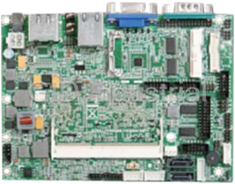
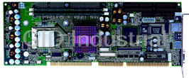
PORTWELL RUBY-9719VG2AR


Specifications
Form Factor
ATX
Ethernet Chipset
Intel 82583V
Video Chipset
Intel GMA Series
Audio
HD Audio interface (Mic-In, Line-In, Line-Out)
BIOS
AMI BIOS
Chipset/Core Logic
Intel G41 and ICH7R
Dimension
305(L) x 244(W) mm; 12"(L) x 9.6" (W)
Display
VGA
Ethernet
Dual Gigabit Ethernet Controller (Intel 82583V x2), Dual RJ-45 connector with two LED indicator at rear I/O panel
Expansion Interface
One PCI-Express x16 slot, One ISA slot and five 32-bit PCI slots, Six 32-bit PCI slots
Graphic Controller
Intel G41 integrated Intel Gen. 5.0 GMA 4500 Graphics, Intel Dynamic Video Memory Technology 5.0, Onboard display: VGA
Hardware Monitoring
System monitor (fan, temperature, voltage)
Keyboard & Mouse
PS/2 keyboard/mouse at rear I/O panel
MIO
Six Powered serial ports: One RS232/422/485 (5V/12V) selectable at rear I/O and Five RS232 (5V/12V) internal, One Parallel port at rear I/O, 8 GPIO internal, LPC pin header for optional TPM module
MTBF
TBD
Operating Temperature
0 to 60oC
Processor
CPU & Package: Intel Core 2 Quad, Intel Core 2 Duo processors in the LGA-775 Land Grid Array package targeted for desktop platforms
Intel Core 2 Quad
Relative Humidity
5% to 95%, non-condensing
Storage Devices
Four SATA 300 ports (RAID 0/1/5/10), One IDE 44-pin connector, One Compact Flash connector (share with IDE channel)
Storage Temperature
-20 to 80oC
System Memory
Max. up to 4GB DDR2 667/800 SDRAM on two 240-pin DIMM sockets with dual channel mode
USB
Eight USB ports (Four ports at rear I/O panel; Four ports internal)
Watchdog Timer
Programmable via software from 1 sec. to 255 min.
Features
- Dual Gigabit Ethernet port
- Four SATA-300 ports support Intel Matrix Storage Technology with RAID 0, 1, 5, 10
- Intel Core 2 Quad / Core 2 Duo Processor and Intel G41 Chipset, FSB up to 1333MHz
- One 40pin IDE and one Compact flash share the same channel
- PCIE x16 slot can support x1, x4, x8 or x16 cards
- Six 32-bit PCI slots / Five PCI slots and One ISA slot
- Two 240-pin DIMMs support dual channel DDR2, SDRAM up to 4GB
Datasheet

Extracted Text
RUBY-9719VG2AR
Industrial Mainboard
User's Manual
Version 1.0
Copyright © Portwell, Inc., 2009. All rights reserved.
All other brand names are registered trademarks of their respective owners.
Preface
Table of Contents
How to Use This Manual
Chapter 1 System Overview.......................................................................................................1-1
1.1 Introduction.................................................................................................................................. 1-1
1.2 Check List ..................................................................................................................................... 1-2
1.3 Product Specification .................................................................................................................. 1-2
1.3.1 Mechanical Drawing......................................................................................................... 1-5
1.4 System Architecture .................................................................................................................... 1-6
Chapter 2 Hardware Configuration ...........................................................................................2-1
2.1 Jumper Setting ............................................................................................................................. 2-1
2.2 Connector Allocation .................................................................................................................. 2-2
Chapter 3 System Installation....................................................................................................3-1
3.1 Intel LGA 775 Processor ............................................................................................................. 3-1
3.2 Main Memory .............................................................................................................................. 3-4
3.3 Installing the Single Board Computer ...................................................................................... 3-5
3.3.1 Chipset Component Driver.............................................................................................. 3-5
3.3.2 Intel Integrated Graphics GMCH Chip.......................................................................... 3-5
3.3.3 On-board Fast Ethernet Controllers................................................................................ 3-6
3.3.4 On-board High Definition Audio Controller ................................................................ 3-6
3.3.5 Intel Matrix Storage Manager Device............................................................................. 3-6
3.4 Clear CMOS Operation............................................................................................................... 3-8
3.5 WDT Programming Guide......................................................................................................... 3-8
3.6 GPIO Programming Guide ......................................................................................................3-10
Chapter 4 BIOS Setup Information............................................................................................4-1
4.1 Entering Setup -- Launch System Setup................................................................................... 4-1
4.2 Main............................................................................................................................................... 4-2
4.3 Advanced...................................................................................................................................... 4-3
4.4 PCIPnP ........................................................................................................................................ 4-20
4.5 Boot.............................................................................................................................................. 4-22
4.6 Security ....................................................................................................................................... 4-26
4.7 Chipset ........................................................................................................................................ 4-27
4.8 Exit............................................................................................................................................... 4-31
4.9 Security ....................................................................................................................................... 4-32
4.10 Chipset ...................................................................................................................................... 4-33
4.11 Exit............................................................................................................................................. 4-38
Chapter 5 Troubleshooting ........................................................................................................5-1
5.1 Hardware Quick Installation ..................................................................................................... 5-1
5.2 BIOS Setting.................................................................................................................................. 5-2
5.3 FAQ ............................................................................................................................................... 5-4
Appendix A
Appendix B
Preface
How to Use This Manual
The manual describes how to configure your RUBY-9719VG2AR system to meet
various operating requirements. It is divided into five chapters, with each chapter
addressing a basic concept and operation of Industrial Main Board.
Chapter 1 : System Overview. Presents what you have in the box and give you an
overview of the product specifications and basic system architecture for this series
model of single board computer.
Chapter 2 : Hardware Configuration. Shows the definitions and locations of
Jumpers and Connectors that you can easily configure your system.
Chapter 3 : System Installation. Describes how to properly mount the CPU, main
and memory to get a safe installation and provides a programming guide of Watch
Dog Timer function.
Chapter 4 : BIOS Setup Information. Specifies the meaning of each setup
parameters, how to get advanced BIOS performance and update new BIOS. In
addition, POST checkpoint list will give users some guidelines of trouble-shooting.
Chapter 5 : Troubleshooting. Provides various useful tips to quickly get RUBY-
9719VG2AR running with success. As basic hardware installation has been
addressed in Chapter 3, this chapter will basically focus on system integration issues,
in terms of backplane setup, BIOS setting, and OS diagnostics.
The content of this manual and EC declaration document is subject to change
without prior notice. These changes will be incorporated in new editions of the
document. Portwell may make supplement or change in the products described in
this document at any time.
Updates to this manual, technical clarification, and answers to frequently asked
questions will be shown on the following web site :
http://www.portwell.com.tw/.
System Overview
Chapter 1
System Overview
1.1 Introduction
Taking advantages of Intel energy-efficient dual-core processing, RUBY-9719VG2AR
® TM TM
ATX Mother Board adopts Intel Core 2 Quad, Core 2 Duo Desktop processors
®
up to 1333 MHz FSB and 4GB DDR2-667/800 system memory. Intel G41 Express
®
chipset with Intel ICH7R RAID function to fit the high performance computer
system applications for meeting today’s demanding pace and keep complete
compatibility with hardware and software designed.
®
RUBY-9719VG2AR comes with the Intel GMA X4500 graphics. The onboard devices
support one PCI Express x16 for an alternative graphics add-on card, six PCI slots
and one ISA expansion is building as standard function.
®
RUBY-9719VG2AR built dual Intel 82583V Gigabit Ethernet controllers offering
stable high-speed networking and supports four SATA 300 ports, eight USB 2.0
ports, one parallel port and one Compact Flash socket (up to UDMA 5 mode), GPIO
and Watchdog timer as usual.
Controller supports six serial ports: five RS-232 powered pin headers, one RS-
232/422/485 powered interface, hardware monitor function, two 6-pin Mini-Din
connectors for PS/2 mouse and keyboard, and one 24-pin standard connector
designed to support ATX power function.
Built with these impressed functions, RUBY-9719VG2AR ATX motherboard are
those ideal solutions for multi-media, gaming, DVR, KIOSK, medical equipment,
industrial automation, semiconductor equipment, and network security markets.
RUBY-9719VG2AR brief specifications:
® ®
� Support Intel Core 2 Quad, Core 2 Duo, Celeron processor in an LGA775
socket
� Dual 240-pin DDR2 SDRAM DIMM socket, support for DDR2 667/800
DIMMs, up to 4GB system memory
®
� Intel G41 integrated GMA X4500 graphics interface
� Dual Gigabit Ethernet port
� Support one Compact Flash socket, six COM ports, four SATA ports and eight
USB 2.0 ports (four ports on real IO)
� PCIex16 Slot (Support PCIex1, PCIex4, PCIex8, PCIex16 Mode, only Graphics
card can be supported, for other requests please contact technical support)
� One ISA slot and five 32-bit PCI slots or Six 32-bit PCI slots
RUBY-9719VG2AR User’s Manual 1-1
System Overview
1.2 Check List
The RUBY-9719VG2AR package should cover the following basic items:
� One RUBY-9719VG2AR Industrial Main Board
� Two SATA 300 cables
� One I/O Shield
� One Installation Resources CD-Title
If any of these items is damaged or missing, please contact your vendor and keep all
packing materials for future replacement and maintenance.
1.3 Product Specification
� Main processor
® ®
- Intel Core 2 Quad / Core 2 Duo/ Celeron Processor
- FSB: 1,333/1,066/800MHz
� BIOS
AMI BIOS
� Main Memory
- Support dual-channel DDR2 memory interface
- Non-ECC, non-buffered DIMMS only
- Two DIMM sockets support 667/800 DDR2-SDRAM up to 4GB System Memory
� Chipset
®
Intel G41 GMCH and ICH7R chipset
� Expansion Interface
- Six 32-bit PCI expansion slots
- One ISA slot Fintek F85226FG LPC to ISA bridge
(By conditions: Fully ISA bridge support except bus master & DMA function)
- PCIex16 Slot (Support PCIex1, PCIex4, PCIex8, PCIex16 Mode, only Graphics
card can be supported, for other requests please contact technical support)
� IDE Interface
One IDE (44pin): Slave
� Compact flash Interface
Support one Type II Compact Flash socket: Master (up to UDMA 5 mode)
� SATA Interface
Four SATA 300 ports
� Serial Ports
Support six serial ports, (RS-232 Powered x 5, RS-232/422/485 selectable
powered x 1)
RUBY-9719VG2AR User’s Manual 1-2
System Overview
� Parallel Port
Support one parallel port
� USB Interface
Support eight USB ports (four ports at rear I/O; four ports internal)
� PS/2 Mouse and Keyboard Interface
Support dual 6-pin mini-DIN connector at rear I/O panel for PS/2
keyboard/mouse
� Audio Interface
3 Audio jacks for Line-in/Line-out/MIC
� Real Time Clock/Calendar (RTC)
Support Y2K Real Time Clock/Calendar with battery backup for 7-year data
retention
� Watchdog Timer
Support WDT function through software programming for enable/disable and
interval setting Generate system reset
� On-board VGA
GMCH integrated Intel Graphics Media Accelerator X4500 (Intel GMA X4500)
� On-board Ethernet LAN
Dual Intel 82583V Gigabit controller to support RJ-45 connector
� High Driving GPIO
Programmable 8-bit Digital I/O interface
� Cooling Fans
Support one 4-pin power connector for CPU cooler and four 3-pin power
connector for system fan
� System Monitoring Feature
Monitor CPU temperature, system temperature and major power sources, etc
� Outline Dimension (L X W):
305mm (12”) X 244mm (9.6”)
� Operating Temperature:
0°C ~ 50°C
� Storage Temperature:
-20°C ~ 80°C
� Relative Humidity:
5% ~ 90%, non-condensing
RUBY-9719VG2AR User’s Manual 1-3
System Overview
� Power Requirements:
Run Burning Test V5.3, RUN time: 10 / 30 Minutes. No Back plane
Full Loading Full Loading
Item Power ON
10Min 30Min
CPU +12V 2.7 3.61 3.57
System +12V 0.42 0.59 0.63
System +3.3V 0.78 1.39 1.47
3.33 5.03 5.25
System +5V
System+ Device +12V 1.77 0.88 0.87
System+ Device +5V 3.45 5.66 5.85
� Configuration:
System Configuration
CPU Type Intel® Core™ 2 Quad CPU Q9400 @2.66GHz L2:6144K
SBC BIOS Portwell, Inc.RUBY-9719 BIOS Rev.:R1.00.E0 (10222009)
Memory Apcer DDR2 800 4GB (ELPIDA E2108ABSE-8G-E)*2
VGA Card Onboard Intel® G41 Express Chipset
VGA Driver Intel® G41 Express Chipset Version 6.14.10.5068
LAN Card
Onboard Intel® 82583V Gigabit Network Chipset
LAN Driver
Intel® 82583V Gigabit Network Connection Version 10.6.15.0
Audio Card
Onboard Realtek ALC662 Audio Chipset
Audio Driver
Realtek High Definition Audio Version 5.10.0.5735
Chip Driver
Intel® Chipset Device Software Version 9.0.0.1008
USB 2.0 Driver
Intel® 82801G (ICH7 Family) USB2 Enhanced Host Controller
Version 8.2.0.1008
SCSI Card Adaptec 29160LP
SCSI HDD Seagate ST39173W 8GB
SATA HDD Seagate ST3120813AS 120GB
Compact Flash Apacer 128MB
CDROM LITE-ON LH-20A1S DVD-ROM
Power Supply
Portwell.Inc PW-330ATXE-12V
RUBY-9719VG2AR User’s Manual 1-4
System Overview
1.3.1 Mechanical Drawing
RUBY-9719VG2AR User’s Manual 1-5
System Overview
1.4 System Architecture
Processor
FSB 1333MHz / 1066MHz / 800MHz
VGA
DDR2
G41
DDR2
PCIeX16 Slot
4G DDR2*2 Long DIMMs
PCI
PCI
PCI
PCIex1
PCI Intel 82583V RJ-45 GbE
PCI
PCI
PCIex1
Intel 82583V RJ-45 GbE
IDE
ICH7R
4 * USB2.0
CF
PATA
4* SATA 2.0
4 * USB2.0
ALC662 Audio Jack
SPI
ISA F85226FG
SPI ROM
5 * COM RS-232
LPC
®
TPM pin header
1 * COM Winbond
RS-232/422/485
83627 UHG
8 bit * GPIO
KB/Mouse
Print port On board
Rear IO
RUBY-9719VG2AR System Block Diagram
RUBY-9719VG2AR User’s Manual 1-6
Hardware Configuration
Chapter 2
Hardware Configuration
This chapter indicates jumpers’, headers’ and connectors’ locations. Users may find
useful information related to hardware settings in this chapter. The default settings
are indicated with a star sign (Ì).
2.1 Jumper Setting
For users to customize RUBY-9719VG2AR’s features. In the following sections, Short
means covering a jumper cap over jumper pins; Open or NC (Not Connected) means
removing a jumper cap from jumper pins. Users can refer to Figure 2-1 for the
Jumper allocations.
Figure 2-1 RUBY-9719VG2AR Jumper & Connector Location
RUBY-9719VG2AR User’s Manual 2-1
Hardware Configuration
The jumper settings are schematically depicted in this manual as follows:
JP1 : RS232, 422, 485 Selection(J2 COM PORT Connector)
JP1 Function
5-6,9-11,10-12,15-17,16-18 Short RS-232 Ì
3-4,7-9,8-10,13-15,14-16,21-22 Short RS-422
1-2,7-9,8-10,19-20 Short RS-485
JP2 : CMOS Clear
JP2 Function
1-2 Short Normal Operation Ì
2-3 Short Clear CMOS Contents
JP3 : Watch Dog Selection
JP3 Function
1-2 Short Enable WDT Ì
1-2 Open Disable WDT
2.2 Connector Allocation
I/O peripheral devices are connected to the interface connectors.
Connector Function List
Connector Function Remark
J1 VGA CONNECTOR
J2 COM2 RS232/422/485 CONNECTOR
J3 Parallel Port CONNECTOR
J4 AUDIO CONNECTOR
J5 KB/MS CONNECTOR
J6 USBX2 + LAN connector
J7 USBX2 + LAN connector
J8 POWER COM2 selection
J9 ATX 4 PIN CONNECTOR
J10 ISA SLOT
J11,J12,J13, PCI SLOT
J14,J15,J16
J17 PCI-E X16 CONNECTOR
J18 COM3 CONNECTOR
J19 POWER COM3 selection
RUBY-9719VG2AR User’s Manual 2-2
Hardware Configuration
J20 COM5 CONNECTOR
J21 POWER COM5 selection
J22 TPM PIN HEADER
J23 CPU FAN CONNECTOR
J24 DDR2 SLOTA
J25 COM4 CONNECTOR
J26 POWER COM4 selection
J27 COM6 CONNECTOR
J28 POWER COM6 selection
J29 GPIO CONNECTOR
J30 DDR2 SLOTB
J31,J32,J35,J36 SATA CONNECTOR
J33 IDE CONNECTOR
J34 COM1 CONNECTOR
J37 POWER BUTTON
J38 POWER COM1 selection
J39 Compact Flash CONNECTOR
J40 ATX 24P CONNECTOR
J41 USBX2 PIN HEADER
J42 USBX2 PIN HEADER
J43 SYSTEM FAN CONNECTOR
Pin Assignments of Connectors
J8 : POWER COM2 selection
Pin No. Signal Description
1-2 short +5v
3-4 short RI#2
5-6 short +12V
J18 : COM3 CONNECTOR
PIN No. Signal Description PIN No. Signal Description
1 DCD#3 2 DSR#3
3 RXD#3 4 RTS#3
5 TXD#3 6 CTS#3
7 DTR#3 8 RI#3
9 GND 10 NC
RUBY-9719VG2AR User’s Manual 2-3
Hardware Configuration
J19 : POWER COM3 selection
PIN No. Signal Description
1-2 short +5v
3-4 short RI-
5-6 short +12V
J20 : COM5 CONNECTOR
PIN No. Signal Description PIN No. Signal Description
1 DCD#5 2 DSR#5
3 RXD#5 4 RTS#5
5 TXD#5 6 CTS#5
7 DTR#5 8 RI#5
9 GND 10 NC
J21 : POWER COM5 selection
PIN No. Signal Description
1-2 short +5V
3-4 short RI#5
5-6 short +12V
J22 : TPM Pin Header
PIN No. Signal Description PIN No. Signal Description
1 PCLK_TPM 2 GND
3 LFRAME# 4 NC
5 PLT_RST# 6 VCC
7 LAD3 8 LAD2
9 VCC3 10 LAD1
11 LAD0 12 GND
13 SMB_CLK 14 SMB_DATA
15 3V_DUAL 16 SERIRQ
17 GND 18 NC
19 LPCPD# 20 NC
RUBY-9719VG2AR User’s Manual 2-4
Hardware Configuration
J23 : CPU Fan connector
PIN No. Signal Description
1 GND
2 +12V
3 SENSE
4 PWM
J25 : COM4 CONNECTOR
PIN No. Signal Description PIN No. Signal Description
1 DCD#4 2 DSR#4
3 RXD#4 4 RTS#4
5 TXD#4 6 CTS#4
7 DTR#4 8 RI#4
9 GND 10 NC
J26 : POWER COM4 selection
PIN No. Signal Description
1-2 short +5V
3-4 short RI#4
5-6 short +12V
J27 : COM6 CONNECTOR
PIN No. Signal Description PIN No. Signal Description
1 DCD#6 2 DSR#6
3 RXD#6 4 RTS#6
5 TXD#6 6 CTS#6
7 DTR#6 8 RI#6
9 GND 10 NC
J28 : POWER COM6 selection
PIN No. Signal Description
1-2 short +5V
3-4 short RI#6
5-6 short +12V
RUBY-9719VG2AR User’s Manual 2-5
Hardware Configuration
J29 : GPIO CONNECTOR
PIN No. Signal Description PIN No. Signal Description
1 GPIO20 2 GPIO60
3 GPIO22 4 GPIO61
4 GPIO24 6 GPIO62
5 GPIO27 8 GPIO63
9 GND 10 +5V
J34 : COM1 CONNECTOR
PIN No. Signal Description PIN No. Signal Description
1 DCD#1 2 DSR#1
3 RXD#1 4 RTS#1
5 TXD#1 6 CTS#1
7 DTR#1 8 RI#1
9 GND 10 NC
J37 : Power Button
PIN No. Signal Description PIN No. Signal Description
1 POWER LED+ 2 NC
3 NC 4 NC
5 POWER LED- 6 NC
7 NC 8 NC
9 NC 10 POWER BUTTON
11 NC 12 POWER BUTTON
13 HD_LED+ 14 RESET
15 HD_LED- 16 RESET
J38 : POWER COM1 selection
PIN No. Signal Description
1-2 short +5V
3-4 short RI#1
5-6 short +12V
RUBY-9719VG2AR User’s Manual 2-6
Hardware Configuration
J41 : USBX2 Pin Header
PIN No. Signal Description PIN No. Signal Description
1 5V_DUAL 2 5V_DUAL
3 D- 4 D-
5 D+ 6 D+
7 GND 8 GND
9 KEY 10 NC
J42 : USBX2 Pin Header
PIN No. Signal Description PIN No. Signal Description
1 5V_DUAL 2 5V_DUAL
3 D- 4 D-
5 D+ 6 D+
7 GND 8 GND
9 KEY 10 NC
J43 : SYSTEM Fan connector
PIN No. Signal Description
1 GND
2 +12V (PWM)
3 SENSE
RUBY-9719VG2AR User’s Manual 2-7
System Installation
Chapter 3
System Installation
This chapter provides you with instructions to set up your system. The additional
information is enclosed to help you set up onboard PCI device and handle Watch
Dog Timer (WDT) and operation of GPIO in software programming.
3.1 Intel LGA 775 Processor
Installing LGA 775 CPU
1) Lift the handling lever of CPU socket outwards and upwards to the other end.
Following step A position to step B position (Figure 3-1).
Figure 3-1
2) Align the processor pins with pinholes on the socket. Make sure that the notched
corner or dot mark (pin 1) of the CPU corresponds to the socket’s bevel end. Then
press the CPU gently until it fits into place (see Fig.3-4). If this operation is not
easy or smooth, don’t do it forcibly. You need to check and rebuild the CPU pin
uniformly.
RUBY-9719VG2AR User’s Manual 3-1
System Installation
Triangle mark is meaning
first pin position; kindly
assemble and take aim at
notch of top and bottom
between CPU and socket.
Figure 3-2
Figure 3-3
Figure 3-4
RUBY-9719VG2AR User’s Manual 3-2
System Installation
Precaution! (See fig.3-3) Don’t touch directly by your hand or impacts internal align
balls of CPU socket to avoid motherboard destruction, it is a precise actuator.
3) Push down the lever to lock processor chip into the socket once CPU fits.
4) Follow the installation guide of cooling fan or heat sink to mount it on CPU
surface and lock it on the LGA 775 package.
5) You should know LGA 775 processor need extra 12V power source.
Don’t forget to connect 4pin 12V connector to PWR1.
PWR1 : Auxiliary CPU Power Connector
PIN No. Description PIN No. Description
1 3
GND P12V_VRD
2 4
GND P12V_VRD
Removing CPU
1) Unlock the cooling fan first.
2) Lift the lever of CPU socket outwards and upwards to the other end.
3) Carefully lifts up the existing CPU to remove it from the socket.
4) Follow the steps of installing a CPU to change to another one or place handling
bar to close the opened socket.
CPU Application
®
Supports Intel Core 2 Quad, Core 2 Duo Desktop processors up to 1333 MHz FSB in
an LGA775 socket.
RUBY-9719VG2AR User’s Manual 3-3
System Installation
3.2 Main Memory
The board also features four DIMM up to 16 GB SDRAM with dual channel DDR2
1066/800.
RUBY-9719VG2AR provide 4 x 240-pin DIMM sockets which supports DDR2
800/1066 MHz as main memory, Non-ECC (Error Checking and Correcting), non-
register functions. The maximum memory size can be up to 16GB capacity.
For system compatibility and stability, do not use memory module without brand.
Memory configuration can be either one double-sided DIMM in either one DIMM
socket or two single-sides DIMM in both sockets.
Watch out the contact and lock integrity of memory module with socket, it will
impact on the system reliability. Follow normal procedures to install memory
module into memory socket. Before locking, make sure that all modules have been
fully inserted into the card slots.
Dual Channel DDR2 DIMM
Dual Channel DDR2 memory technology doubles the bandwidth of memory bus.
Adequate or higher bandwidth of memory than processor would increase system
performance. To enable Dual Channel DDR2 memory technology, you have to
install dual identical memory modules in both memory sockets. Following tables
show bandwidth information of different processor and memory configurations.
CPU FSB Bandwidth
1066MHz 8.5GB/s
800MHz 6.4GB/s
Dual Channel DDR2 Single Channel DDR2
Memory Frequency
Bandwidth Bandwidth
1066MHz 17GB/s 8.5GB/s
800MHz 12.8GB/s 6.4GB/s
Note:
To maintain system stability, don’t change any of DRAM parameters in BIOS setup
to upgrade system performance without acquiring technical information.
RUBY-9719VG2AR User’s Manual 3-4
System Installation
3.3 Installing the Single Board Computer
To install your RUBY-9719VG2AR into standard chassis or proprietary environment,
please perform the following:
Step 1 : Check all jumpers setting on proper position
Step 2 : Install and configure CPU and memory module on right position
Step 3 : Place RUBY-9719VG2AR into the dedicated position in the system
Step 4 : Attach cables to existing peripheral devices and secure it
WARNING
Please ensure that SBC is properly inserted and fixed by mechanism.
Note:
Please refer to section 3.3.1 to 3.3.5 to install INF/VGA/Ethernet/Audio drivers.
3.3.1 Chipset Component Driver
The chipset on RUBY-9719VG2AR is a new chipset that a few old operating systems
might not be able to recognize. To overcome this compatibility issue, for Windows
Operating Systems such as Windows XP, please install its INF before any of other
Drivers are installed. You can select the Intel Chipset driver from the RUBY-
9719VG2AR CD-title.
3.3.2 Intel Integrated Graphics GMCH Chip
®
RUBY-9719VG2AR comes with the Intel GMA X4500 graphics supporting DVMT
5.0 display memory up to 287 MB. Shared 32 accompany it to 128MB system
Memory with Total Graphics Memory. This combination makes RUBY-9719VG2AR
an excellent piece of multimedia hardware.
With no additional video adaptor, this onboard video will usually be the system
display output. By adjusting the BIOS setting to disable on-board VGA, an add-on
PCI-Express by 16 VGA card can take over the system display.
Drivers Support
Please select Intel Graphic driver from the RUBY-9719VG2AR Driver CD-title.
Driver supports Windows XP.
RUBY-9719VG2AR User’s Manual 3-5
System Installation
3.3.3 On-board Fast Ethernet Controllers
Drivers Support
Please select Intel Ethernet driver from the RUBY-9719VG2AR Driver CD-title to
®
install those two integrated Intel 82574L Gigabit Ethernet controller drivers. Those
two drivers support Windows XP.
LED Indicator (for LAN status)
ROBO-8779VG2AR provides two LED indicators to report Intel 82574L & 82574L
Gigabit Ethernet interface status. Please refer to the table below as a quick reference
guide.
Operation of Ethernet Port
82574L
Color Name of LED
&82574L
Linked Active
Status
Orange LAN Linked & Active LED On Blinking
LED
Giga 100 10
Orange
Speed LAN speed LED
Mbps Mbps 1Mbps
LED
Green Orange Green Off
3.3.4 On-board High Definition Audio Controller
Drivers Support
Please select the Realtek High Definition Codec Audio driver from RUBY-
9719VG2AR Driver CD-title. The driver supports Windows XP.
3.3.5 Intel Matrix Storage Manager Device
Drivers Support
Please find utility tool for Intel ICH7R of RUBY-9719VG2AR CD-title. The drivers
support Windows XP.
Installing Serial ATA hard disks
The RUBY-9719VG2AR supports Four Serial ATA hard disk drives. For optimal
performance, install identical drives of the same model and capacity when creating a
disk array.
To install the SATA hard disks for a RAID configuration:
1. Install the SATA hard disks into the drive bays.
2. Connect the SATA signal cables.
3. Connect a SATA power cable to the power connector on each drive.
RUBY-9719VG2AR User’s Manual 3-6
System Installation
Intel RAID configurations
This RUBY-9719VG2AR supports RAID 0, RAID 1, RAID 5, RAID (1+0) and Intel®
Matrix Storage configurations for Serial ATA hard disks drives through the Intel
ICH7R Southbridge chip.
RAID configurations
RAID 0 (Data striping) optimizes two identical hard disk drives to read and write
data in parallel, interleaved stacks. Two hard disks perform the same work as a
single drive but at a sustained data transfer rate, double that of a single disk alone,
thus improving data access and storage. Use of two new identical hard disk drives is
required for this setup.
RAID 1 (Data mirroring) copies and maintains an identical image of data from one
drive to a second drive. If one drive fails, the disk array management software
directs all applications to the surviving drive as it contains a complete copy of the
data in the other drive. This RAID configuration provides data protection and
increases fault tolerance to the entire system. Use two new drives or use an existing
drive and a new drive for this setup. The new drive must be of the same size or
larger than the existing drive.
RAID 5 stripes both data and parity information across three or more hard disk
drives. Among the advantages of RAID 5 configuration include better HDD
performance, fault tolerance, and higher storage capacity. The RAID 5 configuration
is best suited for transaction processing, relational database applications, enterprise
resource planning, and other business systems. Use a minimum of three identical
hard disk drives for this setup.
RAID 10 is data striping and data mirroring combined without parity (redundancy
data) having to be calculated and written. With the RAID 10 configuration you get
all the benefits of both RAID 0 and RAID 1 configurations. Use four new hard disk
drives or use an existing drive and three new drives for this setup.
Intel Matrix Storage Manager. The Intel® Matrix Storage technology supported by
the ICH7R chip allows you to create a RAID 0 and a RAID 1 set using only two
identical hard disk drives. The Intel® Matrix Storage technology creates two
partitions on each hard disk drive to create a virtual RAID 0 and RAID 1 sets. This
technology also allows you to change the hard disk drive partition size without
losing any data.
RUBY-9719VG2AR User’s Manual 3-7
System Installation
3.4 Clear CMOS Operation
The following table indicates how to enable/disable Clear CMOS Function hardware
circuit by putting jumpers at proper position.
JP2 : CMOS Clear
JP2 Function
1-2 Short Normal Operation Ì
2-3 Short Clear CMOS Contents
3.5 WDT Programming Guide
The working algorithm of the WDT function can be simply described as a counting
process. The Time-Out Interval can be set through software programming. The
availability of the time-out interval settings by software or hardware varies from
boards to boards.
RUBY-9719VG2AR allows users to control WDT through dynamic software
programming. The WDT starts counting when it is activated. It sends out a signal to
system reset or to non-maskable interrupt (NMI), when time-out interval ends. To
prevent the time-out interval from running out, a re-trigger signal will need to be
sent before the counting reaches its end. This action will restart the counting process.
A well-written WDT program should keep the counting process running under
normal condition. WDT should never generate a system reset or NMI signal unless
the system runs into troubles.
The related Control Registers of WDT are all included in the following sample
program that is written in C language. User can fill a non-zero value into the Time-
out Value Register to enable/refresh WDT. System will be reset after the Time-out
Value to be counted down to zero. Or user can directly fill a zero value into Time-out
Value Register to disable WDT immediately. To ensure a successful accessing to the
content of desired Control Register, the sequence of following program codes should
be step-by-step run again when each register is accessed.
Additionally, there are maximum 2 seconds of counting tolerance that should be
considered into user’ application program. For more information about WDT, please
refer to Winbond W83627UHG data sheet.
There are two PNP I/O port addresses that can be used to configure WDT,
1) 0x2E:EFIR (Extended Function Index Register, for identifying CR index number)
2) 0x2F:EFDR (Extended Function Data Register, for accessing desired CR)
RUBY-9719VG2AR User’s Manual 3-8
System Installation
Below are some example codes, which demonstrate the use of WDT.
// Enter Extended Function Mode
outp(0x002E, 0x87);
outp(0x002E, 0x87);
// Enable Pin 77 as WDTO#
// Select Logic Device 8
outp(0x002E, 0x07);
outp(0x002F, 0x08);
// Active Logic Device 8
outp(0x002E, 0x30);
outp(0x002F, 0x01);
// Select Count Mode
outp(0x002E, 0xF5);
outp(0x002F, (inp(0x002F) & 0xF7) | ( Count-mode Register & 0x08));
// Specify Time-out Value
outp(0x002E, 0xF6);
outp(0x002F, Time-out Value Register );
// Disable WDT reset by keyboard/mouse interrupts
outp(0x002E, 0xF7);
outp(0x002F, 0x00);
// Exit Extended Function Mode
outp(0x002E, 0xAA);
Definitions of Variables:
Value of Count-mode Register :
1) 0x00 -- Count down in seconds (Bit3=0)
2) 0x08 -- Count down in minutes (Bit3=1)
Value of Time-out Value Register :
1) 0x00 -- Time-out Disable
2) 0x01~0xFF -- Value for counting down
RUBY-9719VG2AR User’s Manual 3-9
System Installation
3.6 GPIO Programming Guide
The RUBY-9719VG2AR provides 8 input/output ports that can be individually
configured to perform a simple basic I/O function. Users can configure each
individual port to become an input or output port by programming register bit of
I/O Selection. To invert port value, the setting of Inversion Register has to be made.
Port values can be set to read or write through Data Register.
The GPIO port is located on J31 shown as follows. Please note: DO NOT SHORT-
CIRCUIT PIN 9 AND 10 OF J31!
J29 : 8-bit GPIO pin header
PIN No. Signal Description PIN No. Signal Description
1 GPIO23 2 GPIO60
3 GPIO22 4 GPIO61
5 GPIO24 6 GPIO62
7 GPIO27 8 GPIO63
9 Ground 10 +5V
All 8 GPIO pins come from W83627UHG, Winbond. All of them are TTL-level, bi-
directional pins and open-drain outputs with 12mA sink capability.
Users can refer to W83627UHG, Winbond datasheet to configure each individual
port to become an input or output port by programming register bit of I/O Selection.
To invert port value, the setting of Inversion Register has to be made. Port values can
be set to read or write through Data Register.
RUBY-9719VG2AR User’s Manual 3-10
BIOS Setup Information
Chapter 4
BIOS Setup Information
RUBY-9719VG2AR is equipped with the AMI BIOS stored in Flash ROM. These
BIOS has a built-in Setup program that allows users to modify the basic system
configuration easily. This type of information is stored in CMOS RAM so that it
is retained during power-off periods. When system is turned on, RUBY-9719VG2AR
communicates with peripheral devices and checks its hardware resources against the
configuration information stored in the CMOS memory. If any error is detected, or
the CMOS parameters need to be initially defined, the diagnostic program will
prompt the user to enter the SETUP program. Some errors are significant enough
to abort the start up.
4.1 Entering Setup -- Launch System Setup
Power on the computer and the system will start POST (Power On Self Test)
process. When the message below appears on the screen, press key to enter
Setup.
Press to enter SETUP
If the message disappears before you respond and you still wish to enter Setup,
restart the system by turning it OFF and On or pressing the RESET button. You
may also restart the system by simultaneously pressing
Frequently asked questions
What makes Portwell Boards unique?

What kind of warranty will the RUBY-9719VG2AR have?
Which carriers does Portwell Boards work with?
Will Portwell Boards sell to me even though I live outside the USA?
I have a preferred payment method. Will Portwell Boards accept it?
Why buy from GID?

Quality
We are industry veterans who take pride in our work

Protection
Avoid the dangers of risky trading in the gray market

Access
Our network of suppliers is ready and at your disposal

Savings
Maintain legacy systems to prevent costly downtime

Speed
Time is of the essence, and we are respectful of yours
Related Products

Portwell 14-4277720 CPU Board. BOARD PEB-2772VGATM 3.5" Atom D2550 | 1.86GHz | Mini PCIe slot | 4GB/...
Portwell 216005080042 CPU Board - Intel Pentium Processor Based Half-Sized ISA CPU
Request a Quote

The quote request has been received
Close

Facing challenges or have inquiries? Feel free to contact us!
Call Us +1-469-283-2440
What they say about us
FANTASTIC RESOURCE
One of our top priorities is maintaining our business with precision, and we are constantly looking for affiliates that can help us achieve our goal. With the aid of GID Industrial, our obsolete product management has never been more efficient. They have been a great resource to our company, and have quickly become a go-to supplier on our list!
Bucher Emhart Glass
EXCELLENT SERVICE
With our strict fundamentals and high expectations, we were surprised when we came across GID Industrial and their competitive pricing. When we approached them with our issue, they were incredibly confident in being able to provide us with a seamless solution at the best price for us. GID Industrial quickly understood our needs and provided us with excellent service, as well as fully tested product to ensure what we received would be the right fit for our company.
Fuji
HARD TO FIND A BETTER PROVIDER
Our company provides services to aid in the manufacture of technological products, such as semiconductors and flat panel displays, and often searching for distributors of obsolete product we require can waste time and money. Finding GID Industrial proved to be a great asset to our company, with cost effective solutions and superior knowledge on all of their materials, it’d be hard to find a better provider of obsolete or hard to find products.
Applied Materials
CONSISTENTLY DELIVERS QUALITY SOLUTIONS
Over the years, the equipment used in our company becomes discontinued, but they’re still of great use to us and our customers. Once these products are no longer available through the manufacturer, finding a reliable, quick supplier is a necessity, and luckily for us, GID Industrial has provided the most trustworthy, quality solutions to our obsolete component needs.
Nidec Vamco
TERRIFIC RESOURCE
This company has been a terrific help to us (I work for Trican Well Service) in sourcing the Micron Ram Memory we needed for our Siemens computers. Great service! And great pricing! I know when the product is shipping and when it will arrive, all the way through the ordering process.
Trican Well Service
GO TO SOURCE
When I can't find an obsolete part, I first call GID and they'll come up with my parts every time. Great customer service and follow up as well. Scott emails me from time to time to touch base and see if we're having trouble finding something.....which is often with our 25 yr old equipment.
ConAgra Foods