

 Manufacturers
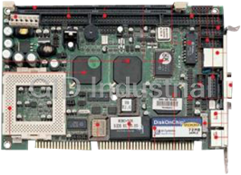
PORTWELL ROBO-3600VLA

Description
VIA Eden/C3 VIA Apollo PN133T 5.25-inch SBC
Part Number
ROBO-3600VLA
Price
Request Quote
Manufacturer
PORTWELL
Lead Time
Request Quote
Category
Single Board Computers
Specifications
Form Factor
EBX
Datasheet

Extracted Text
ROBO-3600VLA VIA Eden/C3 VIA Apollo PN133T 5.25-inch SBC USER’S MANUAL Version 1.2P Acknowledgments Award is a registered trademark of Award Software International, Inc. PS/2 is a trademark of International Business Machines Corporation. Microsoft Windows is a registered trademark of Microsoft Corporation. Winbond is a registered trademark of Winbond Electronics Corporation. All other product names or trademarks are properties of their respective owners. ii ROBO-3600VLA User’s Manual Table of Contents Introduction ..................................................................... 1 Product Description........................................................1 Checklist........................................................................2 Specifications .................................................................3 Board Dimensions ..........................................................4 Installations ..................................................................... 5 Installing the Memory (DIMM).......................................6 Setting the Jumpers.........................................................7 Connectors on ROBO-3600VLA ................................... 12 Watchdog Timer Configuration ..................................... 24 ROBO-3600VLA User’s Manual iii This page was intentionally left blank. iv ROBO-3600VLA User’s Manual INTRODUCTION Introduction Product Description ROBO-3600VLA is a high-performance flexible embedded board based on the VIA ProSavage TwisterT (PN133T) chipset. The chipset is on an innovative and scaleable architecture with proven reliability. It is a two-chip set consisting of the VT8606 North Bridge Controller and VT82C686B South Bridge Controller. ROBO-3600VLA supports the VIA Eden/C3 processors that features Native x86 execution, Integrated full-speed 192KB L1/L2 cache, 100/133MHz Front Side Bus, Advanced multimedia instruction set, and MMX ™ & 3DNow! ™ The VT8606 integrated graphics accelerator supports 8/16/32MB frame buffer using the system memory, integrated 2-channel 110MHz LVDS interface and digital port for NTSC/PAL TV encoder. One or two Ethernets can be supported by the Realtek 8139C single chip Ethernet controller. Additional key features include support for two USB ports, AC-97 link for audio, hardware monitoring, and power management. The VT8606 integrated graphics accelerator supports 8/16/32MB frame buffer using the system memory, integrated 2-channel 110MHz LVDS interface and digital port for NTSC/PAL TV encoder. One or two Ethernets can be supported by the Realtek 8139C single chip Ethernet controller. Additional key features include support for two USB ports, AC-97 link for audio, hardware monitoring, and power management. System memory is provided by one 168-pin DIMM socket that accommodates SDRAM with a maximum capacity of 512MB. The Award BIOS facilitates easy system configuration and peripheral setup. Other advanced features include DiskOnChip flash disk support, 16- level watchdog timer, and IrDA interface. DiskOnChip flash disks are storage devices that have no moving parts and emulate FDD/HDD with Flash/RAM/ROM offering reliable data/program storage and long life span. They are reliable and suitable for industrial or other harsh environments characterized by motion, shock, vibration, adverse temperature, dust and humidity. Other features include faster data access, longer MTBF, lower power consumption, cost effective for small capacity and small form factor. ROBO-3600VLA User’s Manual 1 INTRODUCTION Checklist Your ROBO-3600VLA package should include the items listed below. · The ROBO-3600VLA Embedded Board · This User’s Manual · 1 CD containing chipset drivers and flash memory utility · Optional cables such as: · 1 FDD Ribbon Cable · 1 Audio Cable · 2 IDE Ribbon Cables (40-pin & 44-pin) · 1 COM Port Cable · 1 Printer Port Cable · 1 PS/2 Keyboard/Mouse Cable · 1 VGA Cable · ROBO-3600VLA cable bracket for dual Ethernet 2 ROBO-3600VLA User’s Manual INTRODUCTION Specifications Processor VIA Eden or C3 processors on board Supported 100/133MHz Front Side Bus Chipset VIA Apollo PN133T Chipset North bridge: VT8606 (552-pin BGA package) South bridge: VT82C686B (352-pin BGA package) BIOS Award BIOS Supports ACPI, DMI, PnP System Memory 1x DIMM socket supports up to 512MB capacity PC100/PC133 supported I/O Chipset VT82C686B chipset Keyboard controller built-in I/O Features 1x FDD (up to 2.88MB, 3 Mode, LS120) 2x Parallel Port (EPP, ECP Port) 4x Serial Ports (3x RS232 and 1x RS232/422/485) 1x IrDA TX/RX Headers Bus Master IDE 2x IDE interfaces for up to 4 devices; supports PIO Mode 3/4 or UDMA/33/66/100 HDD, and ATAPI CD-ROM VGA VT8606 integrated graphics controller 8/16/32MB frame buffer with system memory Integrated 2-channel 110MHz LVDS interface Digital port for TV encoder LCD Interface Supports 36 bit TTL LCD interface and 2 channel LVDS TV Out VIA VT1621 TV Encoder (Optional) Composite and S-Video output Audio VT82C686B chipset built-in sound controller With AC97 Codec LAN One or two Realtek RTL8139C Ethernet controllers 10Base-T / 100Base-TX protocol USB 2 ports (pin header) Watchdog Timer 16 levels (0, 2, 4, 6, … 30 sec.) Hardware Built-in VT82C686B chipset Monitoring Monitors CPU/system temperature and voltages DiskOnChip Support M-Systems 2MB~288MB DiskOnChip flash disk Digital I/O 4 in, 4 out Expansion Slot One 32-bit PCI slot One PC/104 expansion slot Power +5V: 8A max. +12V: 750mA max. Consumption Form Factor 5.25-inch SBC Dimensions 203mm x 146mm (7.99” x 5.75”) ROBO-3600VLA User’s Manual 3 INTRODUCTION Board Dimensions 4 ROBO-3600VLA User’s Manual INSTALLATIONS Installations This section provides information on how to use the jumpers and connectors on the ROBO-3600VLA in order to set up a workable system. The topics covered are: Installing the Memory (DIMM).......................................6 Setting the Jumpers.........................................................7 Connectors on ROBO-3600VLA ................................... 12 ROBO-3600VLA User’s Manual 5 INSTALLATIONS Installing the Memory (DIMM) The ROBO-3600VLA Embedded Board supports one 168-pin DIMM socket for a maximum total memory of 512MB in SDRAM type. The memory module capacities supported are 64MB to 512MB. Installing and Removing DIMMs To install the DIMM, locate the memory slot on the Embedded Board and perform the following steps: 1. Hold the DIMM so that the two keys of the DIMM align with those on the memory slot. 2. Gently push the DIMM in an upright position until the clips of the slot close to hold the DIMM in place when the DIMM touches the bottom of the slot. 3. To remove the DIMM, press the clips with both hands. Lock Lock DIMM Lock Lock Top View of DIMM Socket 6 ROBO-3600VLA User’s Manual INSTALLATIONS Setting the Jumpers Jumpers are used on ROBO-3600VLA to select various settings and features according to your needs and applications. Contact your supplier if you have doubts about the best configuration for your needs. Following lists the connectors on ROBO-3600VLA and their respective functions. Jumper Locations on ROBO-3600VLA.................................................8 SW1(3): CPU Bus Speed Selector..........................................................9 JP1, JP4, JP6: RS232/422/485 (COM2) Selection...............................9 JPX2: TV Output Selection......................................................................9 JP2: LAN1 Enable/Disable.....................................................................10 JP3: LCD Power Setting .........................................................................10 JP5: COM3/4 RS232 +5V / +12V Power Setting ..............................10 JP7: COM1/2 RS232 +5V / +12V Power Setting ..............................10 JP8: LAN2 Enable/Disable.....................................................................11 JP9: DiskOnChip Address Select..........................................................11 JP10: AT/ATX Power Selection............................................................11 JP11: Clear CMOS Content ...................................................................11 ROBO-3600VLA User’s Manual 7 INSTALLATIONS Jumper Locations on ROBO-3600VLA Jumpers on ROBO-3600VLA SW1(3): CPU Bus Speed Selector JP1, JP4, JP6: RS232/422/485 (COM2) Selection JPX2: TV Output Selection JP2: LAN1 Enable/Disable JP3: LCD Power Setting JP5: COM3/4 RS232 +5V / +12V Power Setting JP7: COM1/2 RS232 +5V / +12V Power Setting JP8: LAN2 Enable/Disable JP9: DiskOnChip Address Select JP10: AT/ATX Power Selection JP11: Clear CMOS Content 8 ROBO-3600VLA User’s Manual INSTALLATIONS SW1(3): CPU Bus Speed Selector Bus Speed SW1(3) Switch Setting 66MHz off off on on 100MHz off off off on 133MHz off off off off JP1, JP4, JP6: RS232/422/485 (COM2) Selection COM1 is fixed for RS-232 use only. COM2 is selectable for RS232, RS-422 and RS-485. The following table describes the jumper settings for COM2 selection. COM2 RS-232 RS-422 RS-485 Function JP1: JP1: JP1: 3-5 & 4-6 1-3 & 2-4 1-3 & 2-4 Jumper Setting JP4: JP4: JP4: (pin closed) 3-5 & 4-6 1-3 & 2-4 1-3 & 2-4 JP6: JP6: JP6: 1-2 3-4 5-6 JPX2: TV Output Selection JPX2 Setting TV Output Short/Closed TV Output Open LCD Output ROBO-3600VLA User’s Manual 9 INSTALLATIONS JP2: LAN1 Enable/Disable JP2 Setting LAN1 Short/Closed Enabled Open Disabled JP3: LCD Power Setting JP3 Setting Function Pin 1-2 3.3V Short/Closed Pin 2-3 5V Short/Closed JP5: COM3/4 RS232 +5V / +12V Power Setting JP5 Pin # Signal Name JP5 Signal Name JP5 Pin # 1 +5V +5V 2 3 Pin 9 (COM3) Pin 9 (COM4) 4 5 +12V +12V 6 COM3 Settings: Pin 1-3 short = +5V, Pin 3-5 short = +12V COM4 Settings: Pin 2-4 short = +5V, Pin 4-6 short = +12V JP7: COM1/2 RS232 +5V / +12V Power Setting JP7 Pin # Signal Name JP7 Signal Name JP7 Pin # 1 +5V +5V 2 3 Pin 9 (COM1) Pin 9 (COM2) 4 5 +12V +12V 6 COM1 Settings: Pin 1-3 short = +5V, Pin 3-5 short = +12V COM2 Settings: Pin 2-4 short = +5V, Pin 4-6 short = +12V 10 ROBO-3600VLA User’s Manual INSTALLATIONS JP8: LAN2 Enable/Disable JP8 Setting LAN2 Short/Closed Enabled Open Disabled JP9: DiskOnChip Address Select JP9 Setting Address Pin 1-2 D0000-D7FF Short/Closed Pin 2-3 D8000-DFFF Short/Closed JP10: AT/ATX Power Selection JP10 Setting AT / ATX Power Short/Closed Select ATX Power Open Select AT Power JP11: Clear CMOS Content JP11 Setting Function Pin 1-2 Normal Operation Short/Closed Pin 2-3 Clear CMOS Content Short/Closed ROBO-3600VLA User’s Manual 11 INSTALLATIONS Connectors on ROBO-3600VLA The connectors on ROBO-3600VLA allows you to connect external devices such as keyboard, floppy disk drives, hard disk drives, printers, etc. The following table lists the connectors on ROBO-3600VLA and their respective functions. Connector Locations on ROBO-3600VLA......................................... 13 J1: LCD Panel Connector...................................................................... 14 J2, JB2, JC2, JD2: Serial Ports.............................................................. 15 J3, J9: 1st and 2nd Channel LVDS Connector ................................. 16 J4: LCD Inverter Output ........................................................................ 16 J6: Secondary Parallel Port Connector................................................ 16 J7: TV-Out Connector............................................................................ 17 J8: VGA CRT Connector....................................................................... 17 J10: Floppy Drive Connector................................................................ 17 J11: Primary Parallel Port Connector................................................... 18 J12: System Fan Power Connector....................................................... 18 J14: External ATX Power Connector.................................................. 18 J15, J16: LAN1, LAN2 Connector....................................................... 18 J17: System Function Connector.......................................................... 19 J18: Digital I/O......................................................................................... 21 J20: CPU Fan Power Connector........................................................... 21 J21: USB Connector............................................................................... 21 J22: Audio Connector............................................................................. 21 J23: IrDA Connector............................................................................... 22 J24: External Keyboard Connector...................................................... 22 J25, J26: Primary and Secondary IDE Connectors ........................... 22 J27: PS/2 Keyboard/Mouse Connector................................................ 23 J28: CD-in Connector............................................................................. 23 12 ROBO-3600VLA User’s Manual INSTALLATIONS Connector Locations on ROBO-3600VLA J1: LCD Panel Connector J2, JB2, JC2, JD2: Serial Ports J3: 1st Channel LVDS Connector J4: LCD Inverter Output J6: Secondary Parallel Port Connector J7: TV-Out Connector J8: VGA CRT Connector J9: 2nd Channel LVDS Connector J10: Floppy Drive Connector J11: Primary Parallel Port Connector J12: System Fan Power Connector J14: External ATX Power Connector J15, J16: LAN1, LAN2 Connector J17: System Function Connector J18: Digital I/O J20: CPU Fan Power Connector J21: USB Connector J22: Audio Connector J23: IrDA Connector J24: External Keyboard Connector J25, J26: Primary and Secondary IDE Connectors J27: PS/2 Keyboard/Mouse Connector J28: CD-in Connector ROBO-3600VLA User’s Manual 13 INSTALLATIONS J1: LCD Panel Connector J1 is the TTL interface pin header for flat panel LCD displays. The following shows the pin assignments of this connector. Signal Name Pin # Pin # Signal Name +12V 1 2 +12V Ground 3 4 Ground 5V/3.3V 5 6 5V/3.3V ENAVEE 7 8 Ground P0 9 10 P1 B0 11 12 B1 B2 13 14 B3 B4 15 16 B5 P8 17 18 P9 G0 19 20 G1 G2 21 22 G3 G4 23 24 G5 P16 25 26 P17 R0 27 28 R1 R2 29 30 R3 R4 31 32 R5 Ground 33 34 Ground ShfClk(DCLK) 35 36 V. Sync (FLM) MDE(DE) 37 38 H. Sync (LP) Ground 39 40 ENABKL Ground 41 42 NC DNAVDD 43 44 5V/3.3V NC 45 46 NC P24 47 48 P25 P26 49 50 P27 P28 51 52 P29 P30 53 54 P31 P32 55 56 P33 P34 57 58 P35 14 ROBO-3600VLA User’s Manual INSTALLATIONS J2, JB2, JC2, JD2: Serial Ports J2 (COM1), JB2 (COM2), JC2 (COM3) and JD2 (COM4) are the onboard serial ports on the IB795. Pin # Signal Name (RS-232) 1 DCD, Data carrier detect 2 RXD, Receive data 3 TXD, Transmit data 4 DTR, Data terminal ready 5 Ground 6 DSR, Data set ready 7 RTS, Request to send 8 CTS, Clear to send 9 RI, Ring indicator 10 No Connect. JB2 (COM2) is jumper selectable for RS-232, RS-422 and RS-485. Pin # Signal Name RS-232 R2-422 RS-485 1 DCD TX- DATA- 2 RX TX+ DATA+ 3 TX RX+ NC 4 DTR RX- NC 5 Ground Ground Ground 6 DSR RTS- NC 7 RTS RTS+ NC 8 CTS CTS+ NC 9 RI CTS- NC 10 NC NC NC ROBO-3600VLA User’s Manual 15 INSTALLATIONS J3, J9: 1st and 2nd Channel LVDS Connector (DF13-20) Signal Name Pin # Pin # Signal Name TX0- 2 1 TX0+ Ground 4 3 Ground TX1- 6 5 TX1+ 5V/3.3V 8 7 Ground TX3- 10 9 TX3+ TX2- 12 11 TX2+ Ground 14 13 Ground TXC- 16 15 TXC+ 5V/3.3V 18 17 ENABKL +12V 20 19 +12V J4: LCD Inverter Output Pin # Signal Name 1 +12V 2 Ground 3 ENVEE 4 NC 5 Vcc J6: Secondary Parallel Port Connector The following table describes the pin out assignments of this connector. Signal Name Pin # Pin # Signal Name Line printer strobe 1 14 AutoFeed PD0, parallel data 0 2 15 Error PD1, parallel data 1 3 16 Initialize PD2, parallel data 2 4 17 Select PD3, parallel data 3 5 18 Ground PD4, parallel data 4 6 19 Ground PD5, parallel data 5 7 20 Ground PD6, parallel data 6 8 21 Ground PD7, parallel data 7 9 22 Ground ACK, acknowledge 10 23 Ground Busy 11 24 Ground Paper empty 12 25 Ground Select 13 N/A N/A 16 ROBO-3600VLA User’s Manual INSTALLATIONS J7: TV-Out Connector J7 is a 6-pin header for the optional TV-Out connector. Signal Name Pin # Pin # Signal Name Comp 1 2 Ground S-Y 3 4 Ground S-C 5 6 Ground J8: VGA CRT Connector J8 is a 15-pin header for an external VGA CRT female connector. Signal Name Pin Pin Signal Name Red 1 2 Vcc Green 3 4 Ground Blue 5 6 N.C. N.C. 7 8 N.C. Ground 9 10 H-Sync Ground 11 12 V-Sync Ground 13 14 N.C. Ground 15 16 N.C. J10: Floppy Drive Connector J10 is a 34-pin header and will support up to 2.88MB floppy drives. Signal Name Pin # Pin # Signal Name Ground 1 2 RM/LC Ground 3 4 No connect Ground 5 6 No connect Ground 7 8 Index Ground 9 10 Motor enable 0 Ground 11 12 Drive select 1 Ground 13 14 Drive select 0 Ground 15 16 Motor enable 1 Ground 17 18 Direction Ground 19 20 Step Ground 21 22 Write data Ground 23 24 Write gate Ground 25 26 Track 00 Ground 27 28 Write protect Ground 29 30 Read data Ground 31 32 Side 1 select Ground 33 34 Diskette change ROBO-3600VLA User’s Manual 17 INSTALLATIONS J11: Primary Parallel Port Connector The following table describes the pin out assignments of this connector. Signal Name Pin # Pin # Signal Name Line printer strobe 1 14 AutoFeed PD0, parallel data 0 2 15 Error PD1, parallel data 1 3 16 Initialize PD2, parallel data 2 4 17 Select PD3, parallel data 3 5 18 Ground PD4, parallel data 4 6 19 Ground PD5, parallel data 5 7 20 Ground PD6, parallel data 6 8 21 Ground PD7, parallel data 7 9 22 Ground ACK, acknowledge 10 23 Ground Busy 11 24 Ground Paper empty 12 25 Ground Select 13 N/A N/A J12: System Fan Power Connector J12 is a 3-pin header for the system fan. The fan must be a 12V fan. Pin # Signal Name 1 Ground 2 +12V 3 Rotation detection J14: External ATX Power Connector Pin # Signal Name 1 Ground 2 PS-ON (soft on/off) 3 5VSB (Standby +5V) J15, J16: LAN1, LAN2 Connector J15 and J16 are the first and second LAN connectors for RJ45 cables. Signal Name Pin # Pin # Signal Name LED1+ 1 6 LED1- RX+ 2 7 RX- LED2- 3 8 Ground LED2+ 4 9 Ground TX+ 5 10 TX- Note: LED 1: Active LED; LED2: Link LED 18 ROBO-3600VLA User’s Manual INSTALLATIONS J17: System Function Connector J17 provides connectors for system indicators that provide light indication of the computer activities and switches to change the computer status. J17 is a 20-pin header that provides interfaces for the following functions. Hard Disk Drive LED Reset Switch Reserved ATX Power On Switch SMI / Hardware Switch Speaker Power LED Speaker: Pins 1 - 4 This connector provides an interface to a speaker for audio tone generation. An 8-ohm speaker is recommended. Pin # Signal Name 1 Speaker out 2 No connect 3 Ground 4 +5V Power LED: Pins 11 - 13 The power LED indicates the status of the main power switch. Pin # Signal Name 11 Power LED 12 No connect 13 Ground ROBO-3600VLA User’s Manual 19 INSTALLATIONS SMI/Hardware Switch: Pins 6 and 16 This connector supports the "Green Switch" on the control panel, which, when pressed, will force the system into the power-saving mode immediately. Pin # Signal Name 6 Sleep 16 Ground ATX Power ON Switch: Pins 7 and 17 This 2-pin connector is an “ATX Power Supply On/Off Switch” on the system that connects to the power switch on the case. When pressed, the power switch will force the system to power on. When pressed again, it will force the system to power off. Reset Switch: Pins 9 and 19 The reset switch allows the user to reset the system without turning the main power switch off and then on again. Orientation is not required when making a connection to this header. Hard Disk Drive LED Connector: Pins 10 and 20 This connector connects to the hard drive activity LED on control panel. This LED will flash when the HDD is being accessed. Pin # Signal Name 10 Ground 20 5V 20 ROBO-3600VLA User’s Manual INSTALLATIONS J18: Digital I/O Connector (4 in, 4 out) This 12-pin Digital I/O connector supports TTL levels and is used to control external devices requiring ON/OFF circuitry. Signal Name Pin # Pin # Signal Name In0 1 7 +5V In1 2 8 Out0 In2 3 9 Ground In3 4 10 Out1 Ground 5 11 +12V Out2 6 12 Out3 J20: CPU Fan Power Connector J20 is a 3-pin header for the CPU fan power. Pin # Signal Name 1 Ground 2 +12V 3 Rotation detection J21: USB Connector J21 supports an external USB connector with two ports. Pin # Signal Name 1 5 Vcc 2 6 USB- 3 7 USB+ 4 8 Ground J22: Audio Connector J22, a 12-pin header connector, supports an optional external connector supporting 3 sockets for Line Out, Line In and Mic functions. The following table shows the pin assignments of this connector. Signal Name Pin # Pin # Signal Name Line Out R 1 2 Line Out L Ground 3 4 Ground Line In R 5 6 Line In L Ground 7 8 Ground Mic 9 10 BIAS Ground 11 12 NC ROBO-3600VLA User’s Manual 21 INSTALLATIONS J23: IrDA Connector J23 is used for an optional IrDA connector for infrared wireless communication. Pin # Signal Name 1 +5V 2 No connect 3 Ir RX 4 Ground 5 Ir TX J24: External Keyboard Connector J24 is a a 5-pin header for the external keyboard connector. Pin # Signal Name 1 +5V 2 KBCLK-OUT 3 KBCLK-IN 4 KBDAT-OUT 5 KBDAT-IN 6 Ground J25, J26: Primary and Secondary IDE Connectors J25: Primary IDE Connector Signal Name Pin # Pin # Signal Name Reset IDE 1 2 Ground Host data 7 3 4 Host data 8 Host data 6 5 6 Host data 9 Host data 5 7 8 Host data 10 Host data 4 9 10 Host data 11 Host data 3 11 12 Host data 12 Host data 2 13 14 Host data 13 Host data 1 15 16 Host data 14 Host data 0 17 18 Host data 15 Ground 19 20 Protect pin DRQ0 21 22 Ground Host IOW 23 24 Ground Host IOR 25 26 Ground IOCHRDY 27 28 Host ALE DACK0 29 30 Ground IRQ14 31 32 No connect Address 1 33 34 No connect Address 0 35 36 Address 2 Chip select 0 37 38 Chip select 1 Activity 39 40 Ground 22 ROBO-3600VLA User’s Manual INSTALLATIONS J26: Secondary IDE Connector Signal Name Pin # Pin # Signal Name Reset IDE 1 2 Ground Host data 7 3 4 Host data 8 Host data 6 5 6 Host data 9 Host data 5 7 8 Host data 10 Host data 4 9 10 Host data 11 Host data 3 11 12 Host data 12 Host data 2 13 14 Host data 13 Host data 1 15 16 Host data 14 Host data 0 17 18 Host data 15 Ground 19 20 Key DRQ0 21 22 Ground Host IOW 23 24 Ground Host IOR 25 26 Ground IOCHRDY 27 28 Host ALE DACK0 29 30 Ground IRQ14 31 32 No connect Address 1 33 34 No connect Address 0 35 36 Address 2 Chip select 0 37 38 Chip select 1 Activity 39 40 Ground Vcc 41 42 Vcc Ground 43 44 N.C. J27: PS/2 Keyboard/Mouse Connector J27, a 10-pin header connector, has functions for keyboard and mouse. Signal Name Pin # Pin # Signal Name N.C. 10 5 N.C. KB clock 9 4 Mouse clock KB data 8 3 Mouse data Vcc 7 2 Vcc Ground 6 1 Ground J28: CD-in Connector J28 is the 4-pin CD-in connector. Pin # Signal Name 1 Right 2 Ground 3 Ground 4 Left ROBO-3600VLA User’s Manual 23 INSTALLATIONS Watchdog Timer Configuration The function of the watchdog timer is to reset the system automatically and is defined at I/O port 0443H. To enable the watchdog timer and allow the system to reset, write I/O port 0443H. To disable the timer, write I/O port 0441H for the system to stop the watchdog function. The timer has a tolerance of 20% for its intervals. The following describes how the timer should be programmed. Enabling Watchdog: MOVAX, 000FH (Choose the values from 0) MOVDX, 0443H OUT DX, AX Disabling Watchdog MOVAX, 00FH (Any value is fine.) MOV DX, 0441H OUT DX, AX WATCHDOG TIMER CONTROL TABLE Level Value Time/sec Level Value Time/sec 1 F 0 9 7 16 2 E 2 10 6 18 3 D 4 11 5 20 4 C 6 12 4 22 5 B 8 13 3 24 6 A 10 14 2 26 7 9 12 15 1 28 8 8 14 16 0 30 24 ROBO-3600VLA User’s Manual APPENDIX ROBO-3600VLA User’s Manual 25
Frequently asked questions
What makes Portwell Boards unique?

What kind of warranty will the ROBO-3600VLA have?
Which carriers does Portwell Boards work with?
Will Portwell Boards sell to me even though I live outside the USA?
I have a preferred payment method. Will Portwell Boards accept it?
Why buy from GID?

Quality
We are industry veterans who take pride in our work

Protection
Avoid the dangers of risky trading in the gray market

Access
Our network of suppliers is ready and at your disposal

Savings
Maintain legacy systems to prevent costly downtime

Speed
Time is of the essence, and we are respectful of yours
Related Products

Portwell 14-4277720 CPU Board. BOARD PEB-2772VGATM 3.5" Atom D2550 | 1.86GHz | Mini PCIe slot | 4GB/...
Portwell 216005080042 CPU Board - Intel Pentium Processor Based Half-Sized ISA CPU
Request a Quote

The quote request has been received
Close

Facing challenges or have inquiries? Feel free to contact us!
Call Us +1-469-283-2440
What they say about us
FANTASTIC RESOURCE
One of our top priorities is maintaining our business with precision, and we are constantly looking for affiliates that can help us achieve our goal. With the aid of GID Industrial, our obsolete product management has never been more efficient. They have been a great resource to our company, and have quickly become a go-to supplier on our list!
Bucher Emhart Glass
EXCELLENT SERVICE
With our strict fundamentals and high expectations, we were surprised when we came across GID Industrial and their competitive pricing. When we approached them with our issue, they were incredibly confident in being able to provide us with a seamless solution at the best price for us. GID Industrial quickly understood our needs and provided us with excellent service, as well as fully tested product to ensure what we received would be the right fit for our company.
Fuji
HARD TO FIND A BETTER PROVIDER
Our company provides services to aid in the manufacture of technological products, such as semiconductors and flat panel displays, and often searching for distributors of obsolete product we require can waste time and money. Finding GID Industrial proved to be a great asset to our company, with cost effective solutions and superior knowledge on all of their materials, it’d be hard to find a better provider of obsolete or hard to find products.
Applied Materials
CONSISTENTLY DELIVERS QUALITY SOLUTIONS
Over the years, the equipment used in our company becomes discontinued, but they’re still of great use to us and our customers. Once these products are no longer available through the manufacturer, finding a reliable, quick supplier is a necessity, and luckily for us, GID Industrial has provided the most trustworthy, quality solutions to our obsolete component needs.
Nidec Vamco
TERRIFIC RESOURCE
This company has been a terrific help to us (I work for Trican Well Service) in sourcing the Micron Ram Memory we needed for our Siemens computers. Great service! And great pricing! I know when the product is shipping and when it will arrive, all the way through the ordering process.
Trican Well Service
GO TO SOURCE
When I can't find an obsolete part, I first call GID and they'll come up with my parts every time. Great customer service and follow up as well. Scott emails me from time to time to touch base and see if we're having trouble finding something.....which is often with our 25 yr old equipment.
ConAgra Foods